Circuit boards are one of the fundamental components of modern electronic devices. Various electronic components on the circuit board are connected by metal wires, forming complex circuits. Grounding is crucial in these circuits. This article will introduce the basic knowledge related to grounding in circuit boards to help readers better understand the design and manufacturing of circuit boards.
1. Definition and Function of Grounding
The definition of “ground” in electronic technology is: an equipotential point or plane that serves as a reference for the circuit or system.Circuit diagrams and the GND on circuit boards represent the ground wire or zero line. Common types of “ground” in switching power supplies include AC ground, DC ground, analog ground, digital ground, and signal ground.
 Symbol for Ground
Grounding refers to connecting the circuit to the earth to form a reference point for the circuit and a return path for current. The main functions of grounding are to ensure the safety and stability of the circuit. In a circuit, grounding can serve the following purposes:
(1) Protect personnel and equipment in the circuit
By grounding, the current in the circuit can return to the ground, thereby protecting personnel and equipment from hazards such as electric shock.
(2) Suppress electromagnetic interference
In circuit boards, many signal and power lines need to be grounded. These grounding points can eliminate electromagnetic interference between signal and power lines, improving the reliability and stability of the circuit.
(3) Stabilize voltage and current
In circuit boards, grounding can also stabilize voltage and current, keeping them within a certain range.
2. Common Grounding Methods in Circuit Boards
In circuit boards, there are three common grounding methods: single-point grounding, multi-point grounding, mixed grounding, and virtual ground.
(1) Single-point grounding
Single-point grounding refers to connecting all signal and power lines to the same grounding point. This method is the simplest and easiest to implement. However, if the circuit board is large or the current is high, single-point grounding may lead to excessive grounding resistance, affecting the stability and reliability of the circuit. As shown in Figure 2-1:
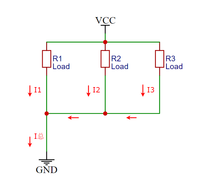 Figure 2-1
(2) Multi-point grounding
Multi-point grounding refers to connecting signal and power lines to different grounding points. This method can effectively reduce grounding resistance and minimize issues such as electromagnetic interference and signal reflection. However, multi-point grounding requires precise control in circuit board design and manufacturing to ensure that the potentials of each grounding point are the same. As shown in Figure 2-2:
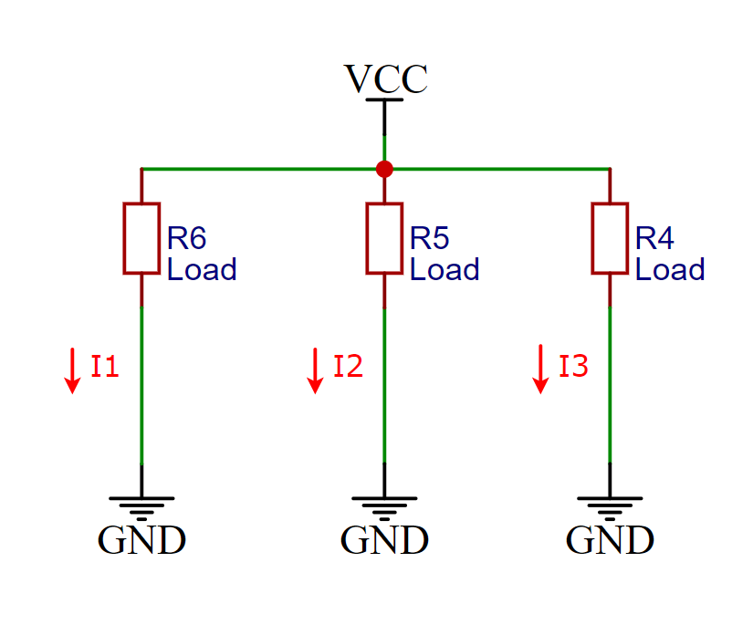 Figure 2-2
(3) Mixed grounding
Mixed grounding combines single-point grounding and multi-point grounding, generally based on single-point grounding with some inductors or capacitors for multi-point grounding. Because inductors and capacitors have different impedances at different frequencies, they form different grounding structures. Mixed grounding is often suitable for circuits operating at mixed frequencies.
(4) Virtual ground
Virtual ground refers to connecting the grounding point to other signal lines instead of an actual ground wire. Virtual ground can eliminate ground loops in circuit board design and reduce electromagnetic interference. However, virtual ground requires precise control and testing to ensure its proper functioning.
3. Grounding Norms and Standards in Circuit Boards
In circuit board design and manufacturing, various grounding norms and standards must be followed to ensure the stability and reliability of the circuit board. Here are some common grounding norms and standards:
(1) IPC-2221B
IPC-2221B is a standard specification for circuit board design, which includes grounding design requirements. This specification requires that in circuit board design, the grounding points for signal and power lines must be as short as possible to reduce grounding resistance and electromagnetic interference.
(2) IPC-A-600
IPC-A-600 is a standard specification for circuit board manufacturing, which includes grounding manufacturing requirements. This specification requires that reliable grounding methods must be used in circuit board manufacturing, avoiding issues such as loose grounding wires and poor contact.
(3) UL Certification
UL certification refers to certification by Underwriters Laboratories, ensuring the safety and reliability of electronic products. Grounding is one of the requirements that must be met in UL certification.
#Recommended Reading#
2025 Munich Shanghai Electronics Show Exhibitor List! (Complete)
Disassembling a 39-dollar smartwatch: Thought it was industrial waste! Unexpectedly powerful, craftsmanship rivals major brands, how did it achieve this?
Disassembling a Fluke multimeter: Truly excellent workmanship, just didn’t expect the main control to use a low-quality chip~