This article focuses on the wake-up, sleep, and reset of the ECU, examining whether your understanding aligns with these concepts.
1. ECU Wake-up
To clarify the ECU wake-up process, we must study the corresponding hardware schematic. The essence of ECU wake-up is to supply power to the ECU. For better understanding, this article simplifies a circuit schematic consisting of Battery (KL30), KL15, SBC (System Basic Chip), uC, and CAN Transceiver, as shown below:
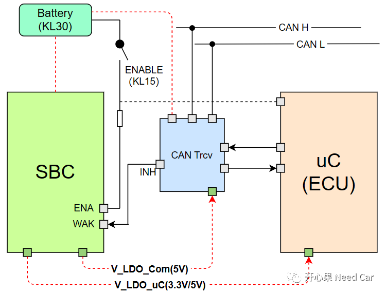
(1) KL15 Wake-up ECU
As shown in the figure, the SBC and CAN Trcv are always connected to the Battery (12V). When the KL15 hard wire is enabled, the ENA pin of the SBC enables the V_LDO_Com and V_LDO_uC voltage outputs. At this point, the CAN Trcv can obtain the communication operating voltage, typically 5V (Vcc). Simultaneously, the ECU receives 3.3V or 5V voltage, and the program begins execution from the reset vector location, at which point the ECU is awakened.
The process of KL15 waking up the ECU (power supply) is illustrated as follows:
Note: The Trcv is always connected to KL30, monitoring the bus. The SBC outputs a 5V communication voltage to the Trcv.(2) BUS Wake-up ECUIn the CAN BUS, when a valid network management message frame is received or the bus presents a wake-up pattern that meets the CAN Trcv’s requirements, the CAN Trcv enables the INH pin. Generally, the INH pin of the Trcv is connected to the WAK pin of the SBC, which then enables the V_LDO_Com and V_LDO_uC voltage outputs. At this point, the CAN Trcv can obtain the operating voltage, typically 5V (Vcc). Simultaneously, the ECU receives 3.3V or 5V operating voltage, and the program begins execution from the reset vector location, at which point the ECU is awakened.The process of the ECU being awakened by the bus message is illustrated as follows:
2. ECU Sleep
For different functions of the ECU, the number and method of wake-up sources may vary, e.g., ECU1 can only be awakened by the bus (e.g., network management message), while ECU2 can be awakened by both the bus and KL15 hard wire. Although different ECUs may have varying wake-up sources and counts, if the ECU wants to enter sleep mode, all corresponding wake-up events must be absent.As previously mentioned, the EcuM phase includes two timing states: SLEEP and OFF. If the ECU enters the SLEEP phase, the ECU is still powered, consuming some energy to monitor wake-up events (e.g., bus NM Msg); if the ECU enters the OFF phase, the ECU is completely powered off, consuming no energy at all. Regardless of whether the ECU enters the SLEEP phase or OFF phase, it is commonly referred to as “ECU sleep” in engineering. During the ECU sleep period, the ECU no longer performs its primary functions and waits to be awakened.
3. ECU Reset
ECU Reset primarily refers to the operational behavior of the software program. There are many types of resets; here we discuss the commonly referred to “ECU Reset” in engineering. When a reset occurs, unlike ECU sleep, the ECU remains powered. The reset action causes the program to “start over,” as shown below:
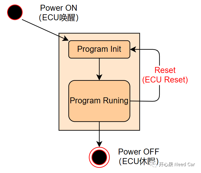
For resets, some are expected, e.g., diagnostic service $10 02/82, $11 xx. Some are unexpected, e.g., program runaway, failing to “feed the watchdog” within the specified time, etc. However, whether the reset is expected or unexpected, the goal is to return the program to its initial state and start again.