Today, I will share with you the DC-DC boost circuit.
This mainly concerns: DC-DC boost circuits, DC-DC boost module principles, and how to construct a DC-DC boost circuit.
1. What is a DC-DC Converter?
A DC-DC converter is a type of power electronics circuit that can effectively convert direct current from one voltage to another.
DC-DC converters play an indispensable role in modern electronic products. This is because they have several advantages over linear regulators. Especially since linear regulators dissipate a lot of heat, they are much less efficient compared to the switch-mode regulators in DC-DC converters.
DC-DC boost circuit
Before introducing the working principle of DC-DC converters, let’s look at an example of why DC-DC converters are so useful. Suppose we want to build a circuit with the following requirements:
DC-DC boost circuit
-
2Ω load resistor
-
12V DC power supply
-
5V load voltage
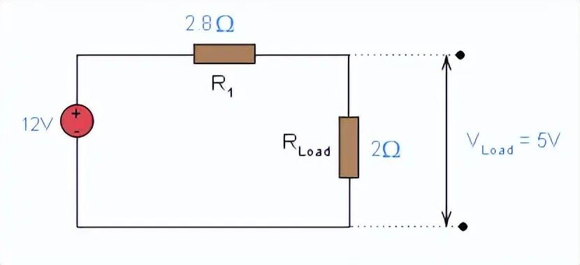
We need to lower the voltage from a 12V battery to provide 5V voltage for the load. We can connect a 2.8Ω resistor in series with the load to provide the required voltage.
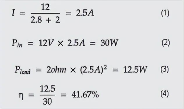
First, let’s calculate the efficiency of the circuit as follows:
DC-DC boost circuit
From these calculations, we can see that the load only consumes 12.5W of input power, and the remaining part (30 – 12.5 = 17.5 W) is converted to heat.
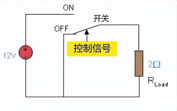
Looking at it this way, it seems a bit wasteful. If you touch the series resistor, it will be a bit warm. Therefore, a mechanism is needed to cool the circuit. For a better solution, see the circuit below:

DC-DC boost circuit
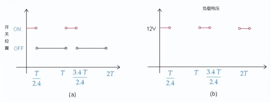
When the switch is off, the input voltage is 0V. When controlled to ON, the input voltage is 12V. The diagram below shows the equivalent circuit for the switch in both ON and OFF positions.
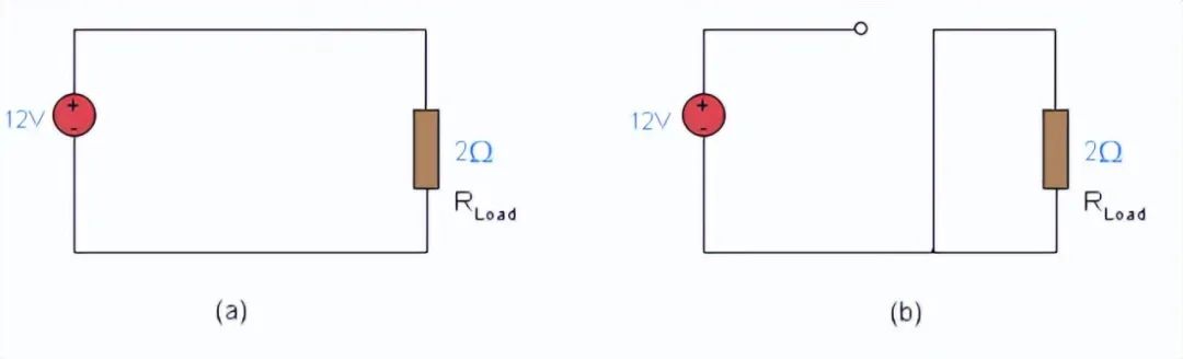
DC-DC boost circuit equivalent circuit
If we control the switch as shown in the diagram (a), we obtain the voltage diagram shown in the diagram (b). T is the switching period, measured in milliseconds or microseconds.
DC-DC boost circuit
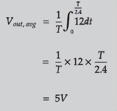
In this case, the average output voltage of this switching behavior is 5V because:
DC-DC boost circuit
The average output voltage of this circuit is 5V, but we can improve the output waveform by using an RC filter to remove harmonics.
If we assume the switch is ideal (an ideal switch is a switch that does not consume or dissipate power), we can calculate that the efficiency of this circuit is 100%. When the switch is in the ON position, the current flowing through the circuit is 6A.
Since we have an ideal switch, the dissipated power is P_diss = RI² = 0 * 9² = 0W. When the switch is in the OFF position, no current flows through the switch, so in this case, the dissipated power is also 0.
However, in practical applications, finding an ideal switch is quite difficult, which means that there will actually be some power loss. Although there is power loss, the conversion efficiency is still very high.
2. DC-DC Boost Circuit
DC-DC boost circuits mainly increase the voltage of the power supply, for example: a boost converter can take a 5V power supply and boost it to 25V. Typically, you will find DC-DC boost converters in battery chargers or solar panels. They can also be used to power components with different operating voltages from the same battery.
This configuration raises the DC voltage to a level determined by the components selected in the circuit. This is a general schematic diagram of a boost converter.
1. Boost Switch ON State
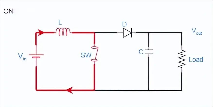
Boost Switch ON State
2. Boost Switch OFF State
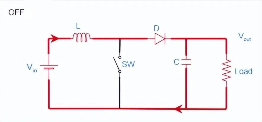
Boost Switch OFF State
The basic configuration includes DC power supply (Vin), inductor (L), diode (D), switching device (SW), smoothing capacitor (C), and load resistor (Load), Vout is the output voltage.
The switch is typically a power electronic device, such as a MOSFET or BJT transistor controlled by a PWM signal. This PWM signal works by rapidly switching the transistor on and off, usually thousands of times per second.
3. Working Principle of DC-DC Boost Circuit
Assuming the current voltage is 5V, and we need to convert 5V to a higher voltage value, this can be achieved with a DC-DC boost circuit. Here we assume we are plumbers.
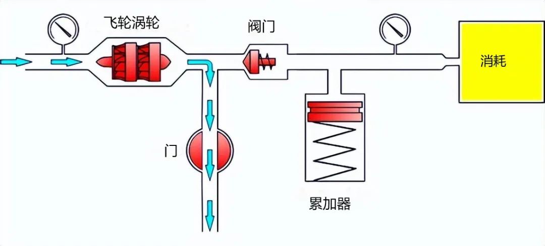
1. Turbo Acceleration
First, we need to accelerate the turbine. To do this, the throttle opens, quickly releasing water and transferring some energy to the turbine, resulting in the turbine starting to rotate.
Working Principle of DC-DC Boost Circuit
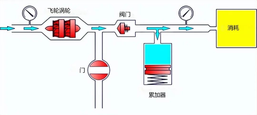
2. Filling the Pressure Tank
The throttle closes, and part of the water, pushed by the rotating turbine flywheel, opens the valve and fills the water tank, while another part of the water flows to the consumer under high pressure provided by the water tank, with the valve preventing backflow.
Working Principle of DC-DC Boost Circuit
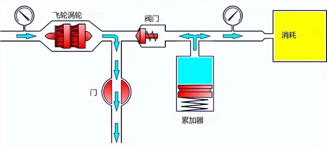
3. Generating Power from the Pressure Tank and Accelerating the Turbine
The speed of the turbine begins to drop. Water can no longer push the valve, but there is still enough energy accumulated in the water tank. Then the throttle opens again, and the water starts to rapidly rotate the turbine. As the consumer receives energy from the tank, the energy flowing to the consumer does not stop, and the cycle repeats.
Now that the working principle is clear, we will switch from plumbing equipment to electronic devices.
Working Principle of DC-DC Boost Circuit
We have replaced the turbine with an inductive throttle. A transistor is used to control the flow of water through the throttle. A diode acts as a valve, while electricity replaces the pressure tank.
Now it is easy to understand the working principle of the DC-DC boost circuit.
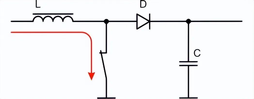
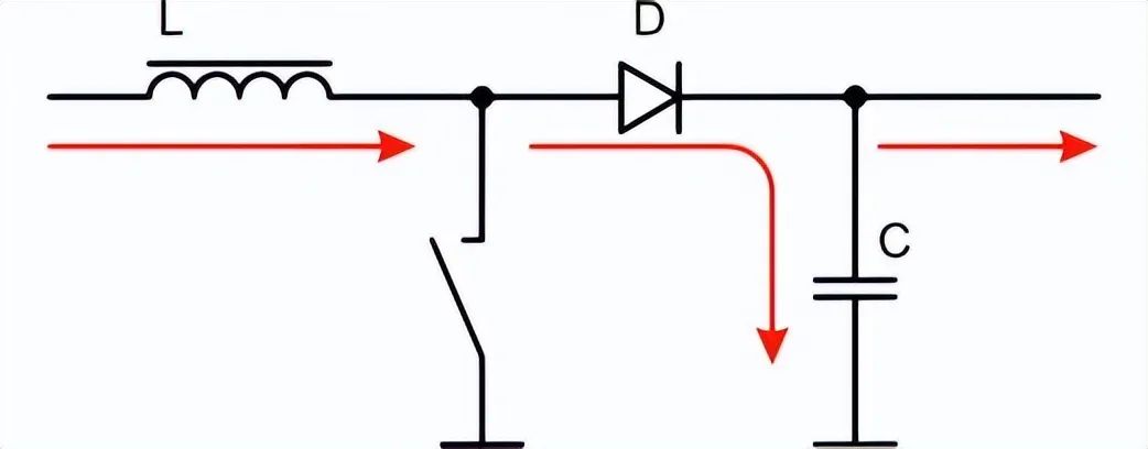
1. Inductor Accumulates Charge
The switch is closed, and the inductor accumulates energy by receiving current from the source.
Working Principle of DC-DC Boost Circuit
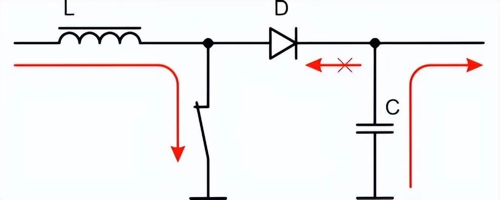
2. Transferring Energy to the Capacitor
The switch opens, and the coil retains the energy accumulated in the magnetic field. The current tries to maintain the same level, but the additional energy from the inductor increases the voltage, thus opening the path through the diode. Part of the energy flows to the consumer, while the remaining energy accumulates in the capacitor.
Working Principle of DC-DC Boost Circuit
3. Accumulating Energy in the Inductor and Transferring Charge to the Consuming Circuit
Then the switch is locked, and the coil starts to accumulate energy again, while the consuming circuit receives energy from the capacitor.
Working Principle of DC-DC Boost Circuit
4. How to Build a DC-DC Boost Circuit
Below, we will build a 1.5V to 5V DC-DC boost converter,
1. Components required to build a DC-DC boost circuit:
-
1.5V DC power supply
-
One 180uH inductor
-
One 1N3491 diode
-
One 33uF capacitor
-
One 150 Ω resistor
-
One MOSFET or JFET switching transistor
-
PWM source, such as Arduino Uno or 555 timer, capable of generating 50KHz, 5V, 75% duty cycle
2. Schematic of the DC-DC boost circuit
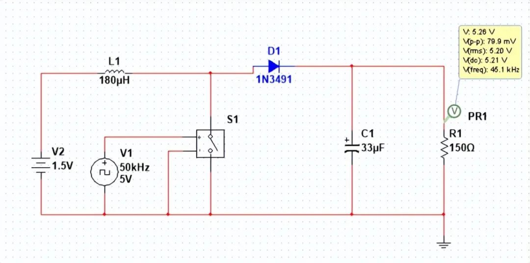
DC-DC boost circuit
That’s all about DC-DC boost circuits. I hope everyone supports us at FindIC, likes, follows, and feel free to leave a message in the comments section if you have any questions, so we can discuss together.