Hello everyone, I am Pi Zi Heng, a serious tech person. Today I will share the method and steps to quickly illuminate a brand new LCD screen on the i.MXRT1170.
As we know, there are many interfaces for LCD screens: DPI-RGB, MIPI DSI, DBI/MCU (I8080), LVDS, SPI, etc. Different interfaces require different software drivers. The RT1170 chip supports all of the above interfaces very well, and today we will mainly discuss the recently popular MIPI DSI interface.
In the official NXP SDK (v2.14), the currently supported LCD screens with MIPI DSI interface include the following four models, but customers often choose various screens in practical applications (there are many manufacturers producing MIPI DSI LCD screens). So, how can we quickly illuminate a brand new LCD screen? Here’s how:
| LCD Model | LCD Resolution | LCD Driver IC |
|---|---|---|
| Crystal Hong Electronics RK055AHD091 | 720×1280 | Ruide Technology RM68200 |
| Crystal Hong Electronics RK055MHD091 | 720×1280 | Qijing Optoelectronics HX8394-F |
| Crystal Hong Electronics RK055IQH091 | 540×960 | Ruide Technology RM68191 |
| Custom Screen G1120B0MIPI | 400×392 | Ruide Technology RM67162 |
1. Preparation Work for Illumination
Sharpening the axe does not delay the work of cutting wood. Before starting the illumination, we need to prepare the following materials, which are very important for subsequent modifications and debugging of the LCD screen-related code. The LCD screen data manual is generally obtained from the screen manufacturer. With the screen data manual, we can find out the corresponding driver IC and then download the data manual for that driver IC.
1. Data manual for the LCD screen<br/>2. Data manual for the built-in driver IC of the LCD screen<br/>3. Schematic diagram of RT1170 board connecting to the LCD screen<br/>4. NXP SDK_2_14_0_MIMXRT1170-EVKB<br/>5. Access to GitHubTaking the KD050FWFIA019-C019A screen produced by Kodak Electronics in Shenzhen as an example, this MIPI DSI screen has a resolution of 480×854, and its driver IC is the ILI9806E from Ilitek Technology.
2. Standard Steps for Illumination
2.1 Familiarize with SDK Standard Example
The elcdif_rgb example in the NXP SDK is a great foundational project that we can modify to debug the code. In this project, we mainly focus on the elcdif_support.c/h files, where NXP has abstracted the differences between different screens. You can find those differences by searching for the MIPI_PANEL_ macro, which indicates the places we need to modify.
\SDK_2_14_0_MIMXRT1170-EVKB\boards\evkbmimxrt1170\driver_examples\elcdif\rgb\cm7\iar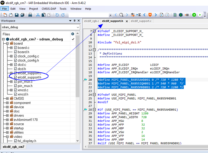
In this elcdif_rgb example, we do not see the G1120B0MIPI because small resolution round screens are not very suitable for this example; its driver can be found in RT595_SDK\boards\evkmimxrt595\vglite_examples.
2.2 Adjust Screen Control I/O Pins (Power_en, Reset, Backlight)
First, let’s focus on the hardware changes that need to be made. The MIPI DSI peripheral (2 Lane) on the RT1170 has many pinmux options, and it has a fixed set of pins (which are dedicated), so we do not need to configure any code for this pin group.
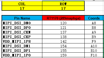
However, besides the MIPI DSI related signals and power, ground, the LCD screen usually has three control signals: Power_en (power enable – optional), Reset (hard reset), Backlight (backlight control). These three signals are generally controlled by ordinary GPIOs.

Therefore, we need to open the board schematic and find the GPIOs used for these three signals and make the necessary changes in the code as follows:

The elcdif_rgb example will operate the GPIO pointed to by the BOARD_MIPI_PANEL_BL macro to turn on the backlight in the shared function BOARD_InitLcdPanel(). Additionally, the operations for BOARD_MIPI_PANEL_RST and BOARD_MIPI_PANEL_POWER macros have been encapsulated in the following functions, which are further encapsulated into display_handle_t for flexible use in subsequent drivers:
static void PANEL_PullResetPin(bool pullUp);<br/>static void PANEL_PullPowerPin(bool pullUp);2.3 Create LCD Driver IC Source File
Now we need to create the driver file for ILI9806E in the following directory. You can first directly copy the files from the hx8394 folder, rename them, and add them to the project, and then also copy and add the corresponding code in elcdif_support.c/h to ensure successful compilation (later modify the code according to the ILI9806E data manual).
\SDK_2_14_0_MIMXRT1170-EVKB\components\video\display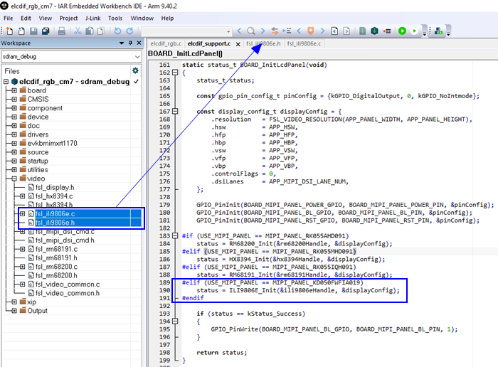
2.4 Adjust Screen Power-On Reset Delay (Power_en, Reset)
With the basic source files for fsl_ili9806e.c/h in place, we now need to modify the code based on the ILI9806E data manual. First, adjust the power-on and reset delay times for the screen. This delay can generally be found in the data manual for the KD050FWFIA019-C019A screen or the ILI9806E data manual.
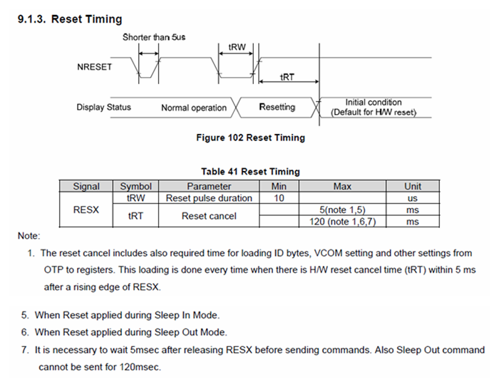
After obtaining the delay values, make the corresponding settings in the ILI9806E_Init() function:
status_t ILI9806E_Init(display_handle_t *handle, const display_config_t *config)<br/>{<br/> const ili9806e_resource_t *resource = (const ili9806e_resource_t *)(handle->resource);<br/> /* Only support 480 * 854 */<br/> if (config->resolution != FSL_VIDEO_RESOLUTION(480, 854))<br/> {<br/> return kStatus_InvalidArgument;<br/> }<br/> /* Power on. */<br/> resource->pullPowerPin(true);<br/> ILI9806E_DelayMs(1U);<br/> /* Adjust reset delay time according to the screen data manual. */<br/> resource->pullResetPin(true);<br/> ILI9806E_DelayMs(10U);<br/> resource->pullResetPin(false);<br/> ILI9806E_DelayMs(10U);<br/> resource->pullResetPin(true);<br/> ILI9806E_DelayMs(120U);<br/> /* Code omitted */<br/>}2.5 Adjust Screen Display Parameters
Now we need to modify the following definitions in elcdif_support.h according to the data manual for the KD050FWFIA019-C019A screen: screen resolution, six row and column scanning parameters, four signal polarities (APP_POL_FLAGS), and data bit width, which are all characteristics of the screen itself.
#if (USE_MIPI_PANEL == MIPI_PANEL_KD050FWFIA019)<br/>#define APP_PANEL_HEIGHT 854<br/>#define APP_PANEL_WIDTH 480<br/>#define APP_HSW 4<br/>#define APP_HFP 18<br/>#define APP_HBP 30<br/>#define APP_VSW 4<br/>#define APP_VFP 20<br/>#define APP_VBP 30<br/>#endif<br/>#define APP_POL_FLAGS \<br/> (kELCDIF_DataEnableActiveHigh | kELCDIF_VsyncActiveLow | kELCDIF_HsyncActiveLow | kELCDIF_DriveDataOnFallingClkEdge)<br/>#define APP_DATA_BUS 24<br/>#define APP_LCDIF_DATA_BUS kELCDIF_DataBus24BitRegarding the six row and column scanning parameters (HSW/HFP/HBP/VSW/VFP/VBP), these signals are delays based on the row and column synchronization signals (VSYNC/HSYNC), effectively expanding the actual displayed image width and height, thereby increasing the reliability of the effective display area (waiting for the panel to prepare for refreshing each row of data).
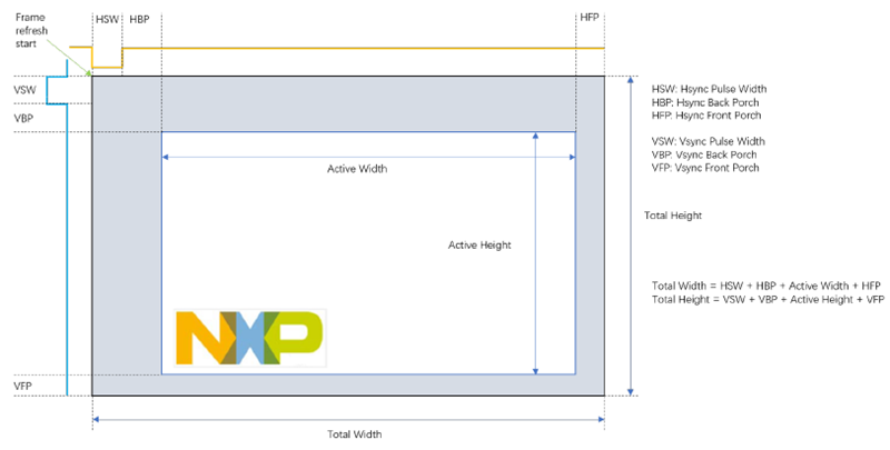
Once the resolution and scanning parameters are set correctly, don’t forget to calculate the required pixel clock based on the desired refresh rate (e.g., 60Hz) and make the corresponding settings in the BOARD_InitLcdifClock() function.
void BOARD_InitLcdifClock(void)<br/>{<br/> /*<br/> * The pixel clock is (height + VSW + VFP + VBP) * (width + HSW + HFP + HBP) * frame rate.<br/> * Use PLL_528 as clock source.<br/> * For 60Hz frame rate, the KD050FWFIA019 pixel clock should be 29MHz.<br/> */<br/> const clock_root_config_t lcdifClockConfig = {<br/> .clockOff = false,<br/> .mux = 4, /*!< PLL_528. */<br/> #if (USE_MIPI_PANEL == MIPI_PANEL_RK055AHD091) || (USE_MIPI_PANEL == MIPI_PANEL_RK055MHD091)<br/> .div = 9,<br/> #elif (USE_MIPI_PANEL == MIPI_PANEL_RK055IQH091)<br/> .div = 15,<br/> #elif (USE_MIPI_PANEL == MIPI_PANEL_KD050FWFIA019)<br/> // We need to set the pixel clock to 29MHz<br/> .div = 18,<br/> #endif<br/> };<br/> CLOCK_SetRootClock(kCLOCK_Root_Lcdif, &lcdifClockConfig);<br/> mipiDsiDpiClkFreq_Hz = CLOCK_GetRootClockFreq(kCLOCK_Root_Lcdif);<br/>}2.6 Configure LCD Driver Chip
Now we come to the most difficult and crucial step. The KD050FWFIA019-C019A panel is primarily driven by the ILI9806E chip, which is a universal driver chip supporting many interfaces, with MIPI DSI being one of them. Moreover, the display-related parameters set in section 2.5 need to be configured into the internal registers of ILI9806E.
Open the ILI9806E data manual (version V097), which has a total of 328 pages, filled with numerous registers. Are we supposed to set them one by one by looking at the data manual? Of course not! At this point, we need to turn to the versatile GitHub and search for code related to ili9806e to see if there are any ready-to-use codes that others have debugged.
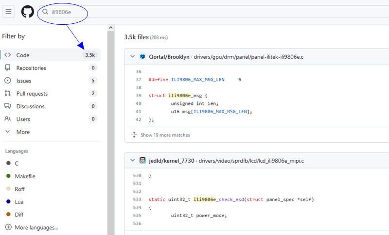
In fact, there is quite a lot of support for screens in Linux. I found a branch ported for Raspberry Pi, which contains the ili9806e parameter initialization table. Note that this table may not be fully applicable to KD050FWFIA019-C019A (as there are many panels driven by ILI9806E), so we need to make some adjustments based on this parameter table.
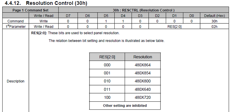
https://github.com/raspberrypi/linux/blob/rpi-6.1.y/drivers/gpu/drm/panel/panel-ilitek-ili9806e.cAfter transplanting the parameter table from the Raspberry Pi repository into our fsl_ili9806e.c file, I briefly looked at the comments, and the configuration was for a 480×800 screen, with polarities set differently from KD050FWFIA019-C019A.
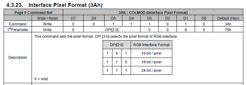
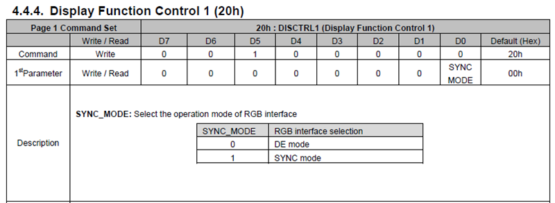
Finally, we need to make some parameter adjustments based on the register definitions in the ILI9806E data manual. The following four registers need to be given special attention. After making these adjustments, download the code to the board and you should see the screen starting to work normally.

Thus, the method and steps to quickly illuminate a brand new LCD screen on the i.MXRT1170 have been introduced.

END
Source: Pi Zi Heng Embedded
Copyright belongs to the original author. If there is any infringement, please contact for deletion.
▍Recommended Reading
Zhi Hui Jun is quietly doing big things again!
Principle of Automatic Baud Rate Recognition in STM32 Serial Port
After writing code for 7 years, I encountered such a ridiculous bug for the first time!