Recently, I started updating a series of articles on the Cortex-M3 core microcontroller, which will cover basic knowledge of assembly, analysis of the startup process, analysis of map files, etc. Further updates will follow, and I welcome friends to follow along.
This is the second article in the series.
1. Understanding and Analyzing Assembly Files
Since the startup code is written in assembly language and contains a large number of directives, I will first introduce the relevant directives before formally presenting the startup code.
1. Directives
Since the assembler used in MDK is the ARM assembler, you can download the user guide from the ARM website for a detailed introduction to directives, or look it up in the assembler user guide in MDK’s Help.
In ARM assembly language programs, there are some special mnemonic instructions that differ from the mnemonic instructions of the instruction set and do not have corresponding opcodes. These special mnemonic instructions are usually referred to as directives, and the operations they perform are called pseudo-operations.
Directives, also known as assembly directives, are special “instructions” provided by the ARM assembler that guide the assembler on how to assemble the program during the assembly process, unlike regular instructions. They are used to prepare for various tasks required to complete the assembly program. Directives do not control the operation of the machine and are not generated into machine code; their mission ends once the assembly process is complete.
 Editor
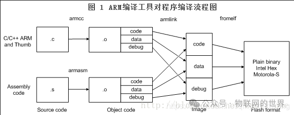 Editor
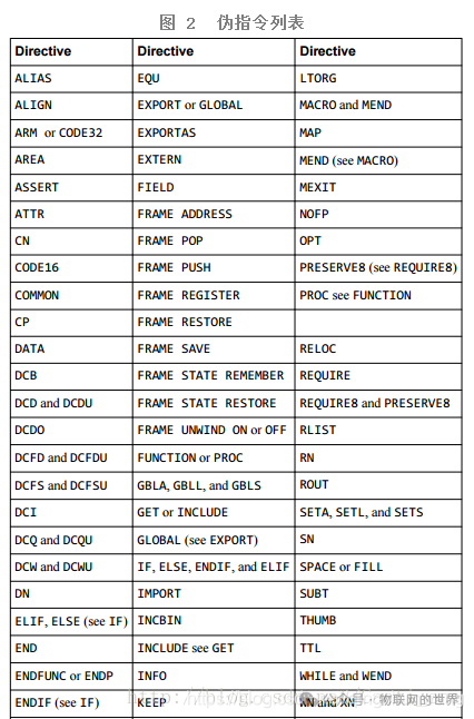
As shown in Figure 2, the ARM assembler provides a variety of directives, which can be categorized based on their functions: symbol definition directives, data definition directives, assembly control directives, macro directives, and others.
 Editor
Next, I will detail the directives used in the startup code:
Note: In assembly language, labels, memory variable names, subroutine names, and macro names are all identifiers.
In assembly language, there are two ways to use labels:
(1) When a label is followed by “:”, it indicates only the memory address;
(2) When a label is not followed by “:”, it indicates both the memory address and the unit length.
● EQU
The EQU directive is used to define a symbolic name for a numeric constant, or a value related to a core register or program counter. It is similar to “#define” in C language.
Syntax: name EQU expr{ , type}
Note: The { } in the syntax is not part of the syntax and the content inside { } is optional.
name: Symbolic name for the value (expr).
expr: An address related to a core register, an absolute address, or a 32-bit integer constant.
type: Optional. It can be any of ARM, THUMB, CODE16, CODE32, or DATA.
For example: fiq EQU 0x1C,CODE32
● AREA
The AREA directive is used to define a code segment or data segment. Whether it is a data segment or a code segment can be distinguished from the attribute name.
Syntax: AREA sectionname{,attr}…{,attr}…
Note: The { } in the syntax is not part of the syntax and the content inside { } is optional.
sectionname: The name of the code or data segment. It is customary to use |.text| for the code segment generated by the C compiler or related to the C library.
It is a separate and indivisible data or code segment that can have any name. However, names that do not start with a letter must begin with an underscore, such as 1_dataarea.
attr: Composed of one or more segment attributes separated by commas.
Segment attributes include: ALIGN=expression, indicating that the data or code segment is aligned to 2^expression bytes;
NOINIT indicates no zero initialization;
READWRITE indicates readable and writable;
DATA indicates operations are only performed on the data segment, which is readable and writable by default.
Note: The DATA directive has been ignored by the compiler, but it can be used as an attribute.
There are other attributes, but I will not elaborate on them here; see the “Assembler User Guide” for details.
● SPACE
The SPACE directive is used to allocate a contiguous block of memory in the storage and initialize it to zero.
Syntax: {label} SPACE expr
Note: The { } in the syntax is not part of the syntax and the content inside { } is optional.
label: It is optional. It can be any character name that does not conflict with the compiler and can be used to indicate the name or function of the allocated memory space.
expr: The size of the zero-initialized memory space allocated, i.e., the number of bytes. It can also be a character with a determined value.
For example: if Stack_Size=0x40, then the statement Stack_Mem SPACE Stack_Size is correct.
● PRESERVE8
The PRESERVE8 directive specifies that the alignment of the stack area in the current file is 8-byte aligned.
Syntax: PRESERVE8 {bool}
Note: The { } in the syntax is not part of the syntax and the content inside { } is optional.
bool: It is optional. It is either true or false, defaulting to true.
● THUMB
The THUMB directive instructs the assembler to translate the instructions following THUMB into T32 instructions using UAL syntax.
Syntax: THUMB
● EXPORT
The EXPORT directive is used to declare a global label in the program that can be referenced in other files.
Syntax: The syntax of EXPORT has 5 forms, and I will mainly introduce 3 forms used in the startup code.
(1) EXPORT { [WEAK]}
(2) EXPORT symbol { [SIZE=n]}
(3) EXPORT symbol [ WEAK {,attr}{type{,set}}{,SIZE=n}]
Note: The { } in the syntax is not part of the syntax and the content inside { } is optional.
[WEAK]: Indicates that other labels with the same name are prioritized over this label. If the symbol is omitted, all labels are considered “WEAK”.
From the startup code, it can be seen that the interrupt service function is weakly declared (marked with the [WEAK] keyword). A weak declaration means that if the user defines the same function, the function in the startup code will be invalid and the user-defined interrupt service function will be used. This is to prevent the user from enabling an interrupt without an interrupt service function, which would cause the program to crash. If the interrupt is enabled and the user has not defined this interrupt service function, it will enter the default interrupt, which is an infinite loop (note: an infinite loop and a program crash are not the same concept).
symbol: It is a globally attributed label, case-sensitive. If the symbol is omitted, all labels are global.
● IMPORT
The IMPORT directive is used to inform the compiler that the label to be used is defined in other source files (i.e., defined in external files, equivalent to extern in C language), but must be referenced in the current source file, and regardless of whether the current source file references this label, it will be added to the symbol table of the current source file. This label is case-sensitive in the program.
Syntax:
(1) IMPORT symbol { [type]}
(2) IMPORT symbol { [SIZE=n]}
(3) IMPORT symbol [WEAK{,attr}…{,type}…{,SIZE=n}]
[WEAK]: The [WEAK] option indicates that when none of the source files define such a label, the compiler will not issue an error message, and in most cases, this label will be set to 0. If this label is referenced by B or BL instructions, the B or BL instruction will be set to a NOP operation.
symbol: It is case-sensitive in the assembly source file, object file, or library file.
● DCD
The DCD directive is used to allocate a contiguous word storage unit and initialize it with specified data. The word storage units allocated by DCD are word-aligned.
Syntax: {label} DCD {U} expr {,expr}
expr: It is a program expression or numeric expression.
● IF ELSE ENDIF
The IF, ELSE, ENDIF directives are used to allow conditional assembly of instructions or directives.
Syntax:
IF logic-expression
Instruction sequence 1
ELSE
Instruction sequence 2
ENDIF
Note: The IF, ELSE, ENDIF directives can determine whether to execute a sequence of instructions based on the truth of the conditional expression. When the logical expression after IF is true, instruction sequence 1 is executed; otherwise, instruction sequence 2 is executed. The ELSE and instruction sequence 2 can be omitted; in this case, when the logical expression after IF is true, instruction sequence 1 is executed; otherwise, the following instructions continue to be executed.
In addition, the IF, ELSE, ENDIF directives can be nested.
The logical expression logic-expression can also be a unary operation (Unary Operator, for details refer to the “Assembler User Guide”). For example, a unary operand :DEF: , :DEF:A indicates that if A is defined, it is true; otherwise, it is false.
● PROC
The PROC directive marks the beginning of a program. It is easy to understand, so I won’t elaborate on it.
● ENDP
The ENDP directive marks the end of a program (call). I won’t elaborate on it here.
● END
The END directive tells the assembler that it has reached the end of the source program file. I won’t elaborate on it here.
2. Assembly Instructions
● B
The B instruction is a jump instruction.
Syntax: B label
In the startup code, you will find that label is a dot “.”, which indicates jumping to the current instruction address (i.e., the current PC value), effectively entering an infinite loop.
● BX
The BX instruction is a jump instruction.
Syntax: BX Rm
Where Rm is a core register whose value is an address. The above instruction indicates that the program jumps to the instruction pointed to by Rm.
● LDR
LDR can be used as a load instruction or as a pseudo-instruction.
As a pseudo-instruction, the syntax is: LDR Rt,=expr. Its function is to load the value of expr (where expr is an immediate value) or the address of expr (where expr is a label) into Rt.
As a load instruction, the syntax is: LDR {type}{cond} Rt, [Rn {, #offset}]. Its function is to load the value from Rn (where Rn’s value is an address) into Rt.
● ORR
The ORR instruction is a logical OR operation instruction.
Syntax: ORR {S} {cond} Rd, Rn, operand2
Where Rn is the first operand, operand2 is the second operand. The above instruction indicates performing a logical OR operation between Rn and operand2, saving the result into the target operand Rd.
● STR
STR is a typical store instruction.
Syntax: STR {type}{cond} Rt, [Rn {, #offset}]. This instruction indicates storing the word data from register Rt into the register at the address of Rn{+offset}.
Note: The { } in the syntax is not part of the syntax, and the content inside { } is optional.
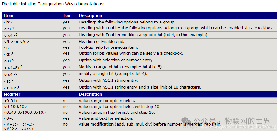
3. Configuration Wizard Comments in the Startup Code
For details on the configuration wizard comments in the startup code, refer to the “uVision User’s Guide” in the Utilities section under “Configuration Wizard”.
Configuration wizard comments are used to generate configuration control in assembly, C/C++, or initialization files.
 Editor
4. Stack Memory
The stack storage area is a data storage area that the user opens up in the on-chip SRAM (or RAM), and the size of the stack area can be specified arbitrarily according to the user’s needs (as long as it does not exceed the size of SRAM or RAM), while the position of the stack area is allocated by the compiler.
The stack pointer SP of the Cortex-M3/M4 processor has the characteristic of “full decrement and empty increment”, exhibiting a downward growth pattern.
The storage characteristic of data in the stack area is “last in, first out”. This characteristic is determined by the movement method of the stack pointer (the pointer value corresponding to the data that enters the stack first is larger, while the pointer value corresponding to the last data to enter the stack is smaller; when popping the stack, the stack pointer value increases, so the data with larger pointer values exits the stack last).
The role of the stack includes: storing local variables, passing data between functions or subroutines during function calls (saving parameters, in fact, once the function call ends, all local variable units defined in the called function will be released), saving现场数据 during function calls, and saving现场数据 when interrupts occur.
4. Analysis of the Startup Code
1. The startup code is located in the installed files of MDK, with the following path: ARM\Pack\Keil\STM32F4xx_DFP\2.11.0\Drivers\CMSIS\Device\ST\STM32F4xx\Source\Templates\arm
2. The function of the startup code:
The execution of a C program starts from the main function main(). But how does the microcontroller find the entry address of the main() function after power-up? Obviously, we cannot find the entry address of the main() function from the hardware. In fact, the entry address of the main() function is allocated by the compiler during the compilation process. Moreover, from the moment the microcontroller powers up to the execution of the main() function, there is a startup process, which is precisely the execution process of the startup code, and this process is very brief.
The functions of the startup code include:
(1) Initializing the stack pointer SP == _initial_sp;
(2) Initializing the PC pointer == Reset_Handler (reset handler);
(3) Initializing the interrupt vector table;
(4) Configuring the system clock;
(5) Calling the C library _main() function to initialize the user stack, ultimately calling the main() function to enter the C world.
The following is the startup code startup_stm32f429xx.s:
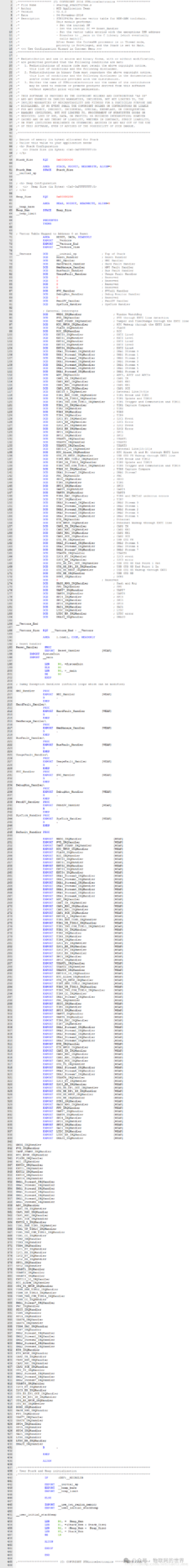 Editor
Lines 48-52: A stack space of size 1KB is defined and initialized to 0 (the stack is also called a stack).
Line 48: A variable Stack_Size is defined and assigned the value 0x00000400;
Line 50: A data segment (or data section) STACK is defined, not zero-initialized, readable and writable, and aligned to 8 bytes;
Line 51: A contiguous memory space of size 0x00000400 (i.e., 1KB) is allocated and initialized to zero, named Stack_Mem;
Line 52: _initial_sp is a label representing the top address of the stack.
Lines 59-64: A heap space of size 0.5KB is defined and initialized to 0. Since the compiler’s built-in memory management (malloc, free, etc.) is not used, the heap size can be set to 0.
Line 59: A variable Heap_Size is defined and assigned the value 0x00000200;
Line 61: A data segment HEAP is defined, not initialized to zero, readable and writable, and aligned to 8 bytes;
Line 62: _heap_base is a label representing the base address of the heap;
Line 63: A contiguous memory space of size 0x000000200 (i.e., 512Bytes) is allocated and initialized to zero, named Heap_Mem;
Line 64: _heap_limit is a label representing the top address of the heap.
Line 66: PRESERVE8 indicates that the stack area in the current file is aligned to 8 bytes;
Line 67: THUMB instructs the assembler to translate the instructions following THUMB into T32.
Lines 71-190: When the system resets, the vector table is mapped to the zero address.
Line 71: A code segment RESET is defined, which is read-only;
Lines 72-74: Three global variables _Vectors, _Vectors_End, and _Vectors_Size are defined;
Lines 76-186: Several contiguous word storage units are defined, which are used to store the vector table. The label _Vectors is the stack top address _initial_sp, and __Vectors_End indicates the end address of the vector table.
Line 188: A variable __Vectors_Size is defined to represent the size of the vector table;
Line 190: A code segment |.text| is defined, which is read-only;
Lines 193-202: The reset handler, which can be modified according to actual conditions.
Line 193: Reset_Handler is a label. PROC indicates the start of the program.
Line 194: A global variable Reset_Handler is defined and specified as [weak] (if the user does not define a function with the same name, then execute the program from lines 195-202).
Lines 195-196: Inform the compiler that SysemInit and _main are two symbols (or function names) defined in other files.
Lines 206-246: Empty exception handler (function entry). Among them, “B .” indicates jumping to the current instruction, thus entering an infinite loop. ENDP indicates the end of the program.
Lines 248-433: Empty exception handlers. The system default handlers and global symbols.
Lines 440-449: User stack and heap initialization program.
Line 440: The IF…ELSE…ENDIF structure. If _MICROLIB is used (or defined), then three global attribute variables are defined. Otherwise, a globally attributed label __user_initial_stackheap is defined, and the compiler is notified that the _use_two_region_memory in this file is defined in other files. Note: The default case of MiCROLIB uses the Keil C library.
Lines 453-460: The stack top address, stack bottom address, heap top address, and heap base address are stored in registers R1, R3, R0, and R2, respectively.
Note: The names of the stack area and heap area represent the starting addresses of the stack area and heap area, respectively. Due to the reverse growth of the stack, its name represents the bottom address of the stack area.
The startup file mainly completes the following tasks, the execution process of the program:
— Set stack pointer SP = __initial_sp
— Set PC pointer = Reset_Handler
— Configure system clock
— Software sets SP
— Load .data, .bss, and initialize stack area
— Jump to __main in the C library, ultimately calling (Call) the user’s main() function
The storage structure of the program in FLASH:
After a hardware reset, the timing logic circuit in the CPU first loads the stack top address stored at 0x08000000 into the SP register; then it loads the vector address stored at 0x08000000 into the PC program counter. The CPU begins executing the program from the physical address pointed to by the PC register, which is the execution of the reset interrupt service program Reset_Handler.
The reset interrupt service program calls the SystemInit() function (in C language) to configure the system clock and configure the external SRAM on the FSMC bus, and then jumps to the __main function in the C library. The __main function in the C library completes the initialization work of the user program (such as assigning initial values to variables, etc.), and then the __main function calls the user-defined main() function to start executing the C program.
Let’s take a look at the file startup_stm32f40_41xxxx.s.
// This statement is equivalent to #define Stack_Size 0x00000400
Stack_Size EQU 0x00000400
AREA STACK, NOINIT, READWRITE, ALIGN=3
Stack_Mem SPACE Stack_Size
__initial_sp
EQU indicates a macro definition directive, similar to #define in C language. The directive means that this “instruction” will not generate binary program code and will not cause variable space allocation.
0x00000400 indicates the stack size, note that this is in bytes.
Allocate a readable and writable data space, segment name STACK, aligned to 8 bytes.
AREA directive indicates that the following will begin to define a code segment or data segment. Here, it defines a data segment. The keywords following AREA indicate the attributes of this segment.
STACK: Indicates the name of this segment, which can be named arbitrarily.
NOINIT: Indicates that this data segment does not need to be filled with initial data.
READWRITE: Indicates that this segment is readable and writable.
ALIGN=3: Indicates that the starting address is aligned to 2 to the power of 3, which means aligned to 8 bytes.
SPACE in this line tells the assembler to allocate 0x0000400 bytes of contiguous memory space for the STACK segment.
__initial_sp is just a label. Here, let me explain what a label is: A label is mainly used to indicate a position in a memory space, equivalent to the “address” concept in C language. An address merely indicates a position in storage space; from the perspective of C language, the addresses of variables, arrays, or function entry points are essentially indistinguishable.
__initial_sp is placed immediately after the SPACE statement, indicating the top address of the stack space. The M4 stack grows from high address space to low address space. When pushing (PUSH), the stack pointer SP decreases. When popping (POP), SP increases. The stack is used to store local variables and save function return addresses.
;
;
;
Heap_Size EQU 0x00000200
AREA HEAP, NOINIT, READWRITE, ALIGN=3
__heap_base
Heap_Mem SPACE Heap_Size
__heap_limit
PRESERVE8
THUMB
Allocate a contiguous memory space for the segment named HEAP, which is the allocated heap space.
The heap size is 0x00000200. The starting address of the heap is aligned to 8 bytes. The heap is mainly used for dynamic memory allocation, meaning that space allocated using the malloc function is located in the heap space.
__heap_base indicates the starting address of the heap.
__heap_limit indicates the ending address of the heap.
PRESERVE8 specifies that the stack area in the current file is 8-byte aligned.
THUMB indicates that the following instructions are THUMB instructions (the CM4 uses a 16-bit THUMB instruction set, which is in contrast to the 32-bit ARM instruction sets of ARM7, ARM9, ARM11).
; Vector Table Mapped to Address 0 at Reset
AREA RESET, DATA, READONLY
EXPORT __Vectors
EXPORT __Vectors_End
EXPORT __Vectors_Size
AREA defines a code segment that is read-only, with the segment name RESET. READONLY indicates read-only, and by default, it is considered a code segment.
Three EXPORT statements declare three labels as externally referenceable, mainly provided to the linker for connecting library files or other files.
__Vectors DCD __initial_sp ; Top of Stack
DCD Reset_Handler ; Reset Handler
DCD NMI_Handler ; NMI Handler
DCD HardFault_Handler ; Hard Fault Handler
DCD MemManage_Handler ; MPU Fault Handler
DCD BusFault_Handler ; Bus Fault Handler
DCD UsageFault_Handler ; Usage Fault Handler
······省略······
DCD DCMI_IRQHandler ; DCMI
DCD CRYP_IRQHandler ; CRYP crypto
DCD HASH_RNG_IRQHandler ; Hash and Rng
DCD FPU_IRQHandler ; FPU
__Vectors_End
__Vectors_Size EQU __Vectors_End – __Vectors
A vector table is established, and the interrupt vector table is positioned at the front of the code segment. The specific physical address is determined by the configuration parameters of the linker (the address of IROM1). If the program runs in Flash, the starting address of the interrupt vector table is 0x08000000.
DCD indicates allocating 1 space of 4 bytes. Each DCD line generates a 4-byte binary code. The interrupt vector table actually stores the entry addresses of the interrupt service programs. When an exception (i.e., an interrupt event) occurs, the CPU’s interrupt system assigns the corresponding entry address to the PC program counter, and then begins executing the interrupt service program.
AREA |.text|, CODE, READONLY
; Reset handler
Reset_Handler PROC
EXPORT Reset_Handler [WEAK]
IMPORT SystemInit
IMPORT __main
LDR R0, =SystemInit
BLX R0
LDR R0, =__main
BX R0
ENDP
… The following are other interrupt service programs …
; Dummy Exception Handlers (infinite loops which can be modified)
NMI_Handler PROC
EXPORT NMI_Handler [WEAK]
B . <—— Infinite loop, the user can write their own interrupt service program
ENDP
HardFault_Handler
bsp;
PROC
EXPORT HardFault_Handler [WEAK] B .
ENDP
… The middle code has been omitted …
Default_Handler PROC <—— Default interrupt service program (start)
EXPORT WWDG_IRQHandler [WEAK]
EXPORT PVD_IRQHandler [WEAK]
… The middle code has been omitted …
CRYP_IRQHandler
HASH_RNG_IRQHandler
FPU_IRQHandler
B . <—— Infinite loop
ENDP <—— Default interrupt service program (end)
The interrupt service program implemented in assembly language focuses on the reset interrupt service program.
Using the PROC and ENDP directives, the program segment is divided into several processes, making the program structure clearer.
WEAK indicates that other labels with the same name are prioritized over this label, meaning that if an external declaration exists, it will call the external one. This declaration is important as it allows us to place interrupt service programs anywhere in the C file, as long as we ensure that the names of the C functions are consistent with the names in the vector table.
IMPORT: The directive is used to inform the compiler that the label to be used is defined in other source files. However, it must be referenced in the current source file, and regardless of whether the current source file references this label, it will be added to the symbol table of the current source file.
The SystemInit function is in the file system_stm32f4xx.c, which will be detailed in the next tutorial.
Here, I would like to emphasize the __main label; the __main label does not represent the entry address of the main function in the C program. Therefore, LDR R0,=__main does not jump to the beginning of the main function to start executing the C program. The __main label indicates the entry address of an initialization subroutine __main in the C/C++ standard runtime library.
The main function of the __main program is to initialize the stack (jumping to the __user_initial_stackheap label for stack initialization, which will be discussed below), and to initialize the image file, then jump to the main function in the C program. This explains why all C programs must have a main function as the starting point of the program. This is dictated by the C/C++ standard runtime library and cannot be changed.
;*******************************************************************************
; User Stack and Heap initialization
;*******************************************************************************
IF :DEF:__MICROLIB
EXPORT __initial_sp
EXPORT __heap_base
EXPORT __heap_limit
ELSE
IMPORT __use_two_region_memory
EXPORT __user_initial_stackheap
__user_initial_stackheap
LDR R0, = Heap_Mem
LDR R1, =(Stack_Mem + Stack_Size)
LDR R2, = (Heap_Mem + Heap_Size)
LDR R3, = Stack_Mem
BX LR
ALIGN
ENDIF
END
;************************ (C) COPYRIGHT STMicroelectronics *****END OF FILE*****