Recently started updating a series of articles on Cortex-M3 core microcontrollers, which will involve basic knowledge of assembly, analysis of the startup process, map file analysis, etc. Further updates will continue, and friends are welcome to follow.
This is the fourth article
Other already updated series articles include 104, 61850, etc., welcome to read.
Variable Reference
IMPORT OSRunning
IMPORT OSPrioCur
IMPORT OSPrioHighRdy
IMPORT OSTCBCur
IMPORT OSTCBHighRdy
IMPORT OSIntNesting
IMPORT OSIntExit
IMPORT OSTaskSwHook
EXPORT OSStartHighRdy
EXPORT OSCtxSw
EXPORT OSIntCtxSw
EXPORT OS_CPU_SR_Save ;
EXPORT OS_CPU_SR_Restore
/*****************PendV_Handler modified***********************/
EXPORT PendSV_Handler
The use of IMPORT defines indicates that this is an external label, not defined in this file, and EXPORT indicates that these labels are defined in this file and can be called by other external files.
The EXPORT keyword is related to the compiler, recognized by Keil, but not recognized by IAR.
Constant Definition
/*********Address of Interrupt Control and State Register ICSR*******************/
NVIC_INT_CTRL EQU 0xE000ED04
/************Address of System Priority Register***************************/
NVIC_SYSPRI2 EQU 0xE000ED20
/************PendSV Interrupt and System Tick Interrupt**********************/
NVIC_PENDSV_PRI EQU 0xFFFF0000
/************Value to Trigger Software Interrupt*******************************/
NVIC_PENDSVSET EQU 0x10000000
EQU instruction is similar to #define in C language,
Here it involves interrupt control and state register NVIC_INT_CTRL, system exception priority register NVIC_SYSPR12, and PendSV interrupt.
Supplement on the specific behavior of the MCU after generating an interrupt:
When the CM3 starts to respond to an interrupt, three undercurrents surge within it that are invisible:
Push: Push the values of 8 registers onto the stack
Fetch vector: Find the corresponding service program entry address from the vector table
Select stack pointer MSP/PSP, update stack pointer SP, update link register LR, update program counter PC
Push
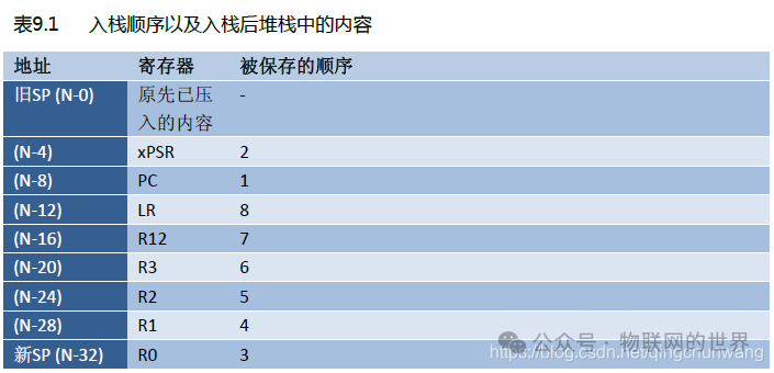
The first action in response to an exception is to automatically save the necessary parts of the scene: sequentially push xPSR, PC, LR, R12, and
R3-R0 automatically into the appropriate stack: if the current code is using PSP when responding to an exception, it will push
PSP, that is, using the thread stack; otherwise, it will push MSP, using the main stack. Once entering the service routine, it will continue to use
the main stack.
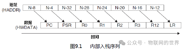
Assuming the value of SP at the start of the push is N, then after the push, the internal changes of the stack are as shown in Table 9.1. Also, due to the nature of the pipeline operation on the AHB
interface, addresses and data only enter after one pipeline cycle. Additionally, this push operation within the machine does not strictly follow the order of stack operations—but the machine will ensure that the correct registers will be
saved in the correct positions, as shown in the third column of Table 9.1.
Fetch vector
When the data bus (system bus) is busy with the push operation, the instruction bus (I-Code bus) cannot sit idly by— it is busily executing another important task in an orderly manner: fetching the correct exception vector from the vector table and prefetching instructions at the service program entry. Thus, we can see the benefits of having dedicated buses: the push and fetch operations can be performed simultaneously.
Update registers
After the push and fetch operations are completed, before executing the service routine, a series of registers need to be updated:
SP: The stack pointer (PSP or MSP) will be updated to the new location during the push. After executing the service routine,
MSP will be responsible for accessing the stack.
PSR: The IPSR bit field (located at the lowest part of PSR) will be updated to the new exception number being responded to.
PC: After the vector is fetched, PC will point to the entry address of the service routine,
LR: The usage of LR will be reinterpreted, and its value will also be updated to a special value called “EXC_RETURN,”
which will be used upon exception return. The binary value of EXC_RETURN is all 1s except for the lowest 4 bits, which have different meanings (discussed later, see Tables 9.3 and 9.4).
The above describes the changes to general registers in response to exceptions. On the other hand, in NVIC, several related registers are also updated. For example, the pending bit of the newly responded exception will be cleared, while its active bit will be set.
Exception return
After the exception service routine is completed, a formal “exception return” action sequence is needed to restore the previous system state so that the interrupted program can continue executing. Formally, there are three ways to trigger the exception return sequence, as shown in Table 9.2; regardless of which is used, the value of LR previously stored is needed.
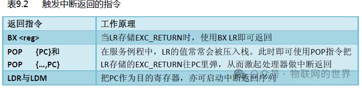
Some processors use special return instructions to indicate interrupt returns, such as 8051 using reti. However, in CM3,
the return action is recognized by writing EXC_RETURN to PC. Therefore, conventional return instructions can be used,
which clears the last obstacle for writing service routines in C language (no special compiler commands, such as __interrupt).
After starting the interrupt return sequence, the following processing will occur:
1. Pop: The registers previously pushed onto the stack will be restored here. The internal pop order corresponds to the push order, and the value of the stack pointer will also be reverted.
2. Update NVIC registers: Along with the exception return, its active bit is also cleared by hardware. For external interrupts, if
the interrupt input is set to valid again, the pending bit will also be set again, allowing a new interrupt response sequence to begin.
Specific analysis of why ucosii involves PendSV interrupts
Modern CPUs operate according to the instruction pointer pc. When ucos performs task switching, if a high-priority task is ready, it will interrupt the currently running low-priority task during task scheduling. To ensure that the high-priority task can resume execution from the point where the low-priority task was interrupted, the program pointer at the breakpoint needs to be pushed onto the stack. After the high-priority task ends, the program pointer at the breakpoint can be popped back to the program pointer PC from the stack, achieving seamless task switching. However, most CPUs do not have instructions for pushing and popping the pc register onto the stack, so when ucosii performs task switching, it needs to consider detouring operations to rewrite the pc register. Fortunately, modern CPUs have an interrupt handling mechanism that allows for rewriting the pc register. When the CPU responds to an interrupt, the system automatically pushes the breakpoint pointer onto the stack, and the interrupt return instruction automatically pops the breakpoint pointer from the stack back to the pc register, restoring the interrupted program, thus protecting and restoring the breakpoint.
Ucosii uses this mechanism. When a task switch is needed, it triggers an interrupt through a soft instruction, indirectly saving and restoring the pc register. Of course, stm32 also saves and restores other registers besides the pc during the interrupt response process, but not all of them. The interrupt triggered by ucosii is the PendSV interrupt. During the task switch, it only needs to trigger the PendSV interrupt through a soft instruction. In the PendSV interrupt service program, the context of the interrupted task is protected, and the context of the task to be run is restored. At the same time, the CPU automatically rewrites the pc pointer during the interrupt response process, thus perfectly achieving task switching by tricking the CPU to rewrite the pc register.
NVIC_INT_CTRL:
The address is 0xE000ED04. This register can set a pending NMI, set or clear a pending PendSV, set or clear a pending systick, find pending exceptions, etc. For ucos porting, the relevant bit of this register is bit 28, which is PENDSVSET. When set to 1, it will suspend PendSV, and 0 will not suspend it. Therefore, when needing to trigger a PendSV interrupt through a soft instruction, NVIC_PENDSVET can be written to the interrupt control status register NVIC_INT_CTRL.
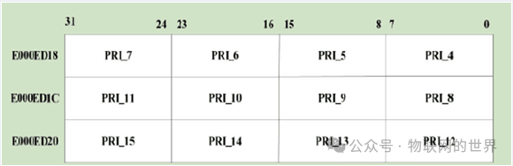
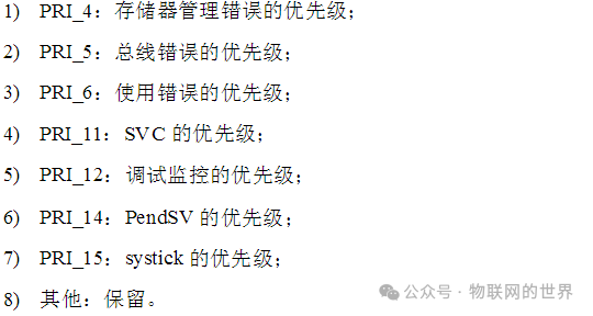
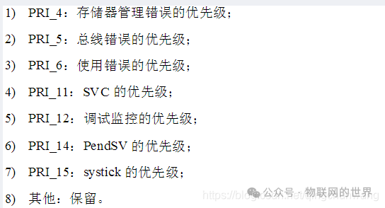
NVIC_SYSPRI2:
The system exception priority is used to set the priority of system exceptions, with an address range of 0xE000ED81-0xE000ED23.
The distribution map of the system exception priority register bits

Switch Interrupts
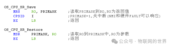
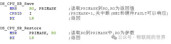
The above two code segments are the program segments for switching interrupts. The OS_CPU_SR_Save segment is the program segment for turning off interrupts and returning the value of the PRIMASK register. The OS_CPU_SR_Restore segment is for writing back the saved interrupt switch state from the stack to the PRIMASK register.
Before calling this function, a local variable cpu_sr must be defined, saving the CPU state before entering the interrupt and restoring it after exiting.
[Image][Image]Edit[Image][Image]Edit
Scheduler
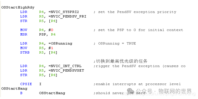
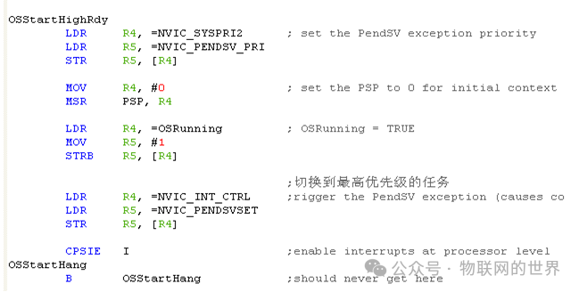
The OSStartHighRdy program segment is called by ucos’s OSStart to run the first highest priority task, provided that the task has been created.
The program first sets the PendSV priority, sets the PSP stack pointer, and sets the system running flag OSRunning.
Then it triggers the PendSV interrupt through a soft instruction. In the PendSV interrupt service program, the task context protection and switching are realized, thus completing task scheduling and starting to run the first program.
The first segment: Set the systick priority and the PendSV priority to 0xFF, which means setting the lowest priority.
The second segment: Set the stack pointer PSP to 0, because this is the first program running in the system. In the PendSV interrupt service program, there is no need to maintain the running environment of the previous task (there is no previous task). Here, setting PSP to 0 informs the PendSV interrupt service program that there is no need to save the running environment of the previous task. In the PendSV interrupt service program, the value of PSP will be checked, which will be analyzed later.
The third segment: Set the system running flag OSRunning to indicate that it is running.
The fourth segment: Trigger the PendSV interrupt by setting the interrupt control status register NVIC_INT_CTRL, and then implement task switching in the PendSV interrupt service program. When exiting the interrupt service program, the system will automatically write the pointer of the first task into the PC register, starting to run the code of the first task.
The fifth segment: Enable interrupts and trigger the PendSV interrupt.
Task Level Up and Down Switching
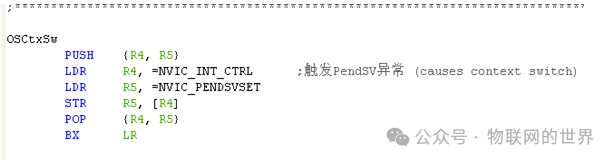
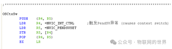
OSCtxSw is the task-level context switching program segment, which is encapsulated in the OS_TASK_SW() macro in os_cpu.h.
[Image][Image]Edit[Image][Image]Edit
The OSCtxSw program segment simply triggers the PendSV interrupt by setting the interrupt control status register, and then returns. When the PendSV interrupt is triggered in OSCtxSw, the PendSV interrupt service program will not run immediately because interrupts are disabled when calling OS_TASK_SW(). Only after enabling interrupts will the PendSV interrupt service program have the opportunity to run.
Generally, the OS_Sched function calls the OS_TASK_SW() macro.
Interrupt Level Up and Down Switching
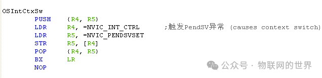
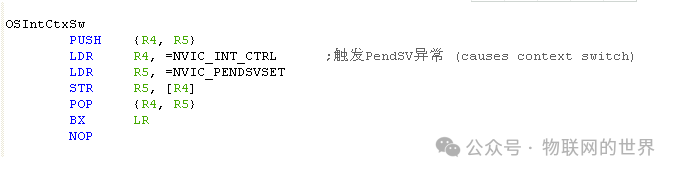
OSIntCtxSw is the interrupt-level context switching program segment. After an interrupt service program ends, OSIntExit() checks if there are any higher priority programs ready. If so, it calls the OSIntCtxSw program segment to perform task switching. OSIntCtxSw also simply triggers the PendSV interrupt by setting the interrupt control status register and then returns.
OSIntCtxSw has the same code as OSCtxSw, but the significance is different. OSCtxSw is task-level switching (e.g., task A switches to task B due to waiting for some resource or timing out), while OSIntCtxSw is interrupt-level switching (switching to another task from the interrupt state). At this time, the running environment of the task interrupted by the interrupt has been cached in the stack, so there is no need to push the running environment of the interrupted task onto the stack again when switching from the interrupt to the new task.
PendSV Interrupt
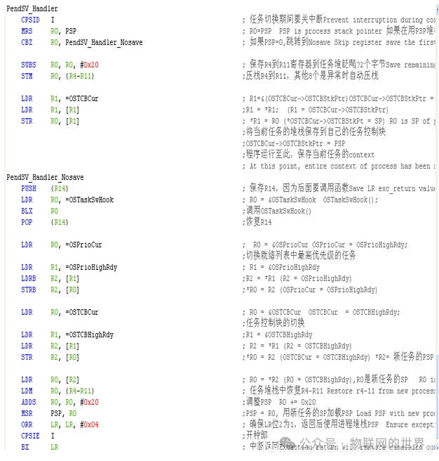
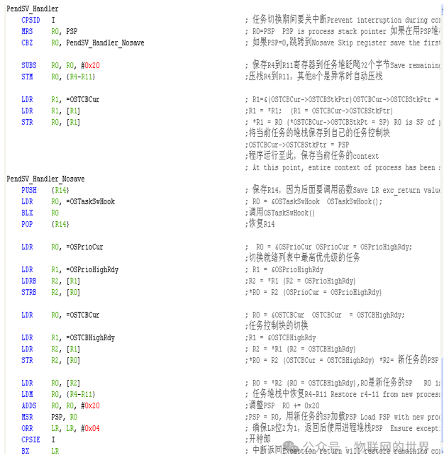
The interrupt service program implements task switching using assembly language. The CM3 architecture processor automatically pushes the registers xPSR, PC, LR, R12, R3, R2, R1, R0 onto the stack when responding to an interrupt, and automatically pops these 8 registers from the stack when exiting the interrupt. The remaining registers R4-R11 need to be pushed onto the stack by the program. Therefore, the PendSV interrupt service program needs to push and pop the R4-R11 registers onto and from the stack.
To facilitate understanding, let’s look at the pseudo code of PendSV_Handler.
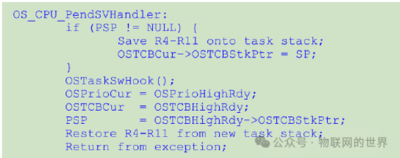

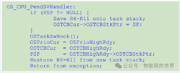
First, check if the PSP stack pointer is NULL. If PSP is 0, it indicates that the first task of the system will run, and there is no need to cache the R4-R11 registers. Otherwise, R4-R11 registers need to be cached (i.e., the running environment of the previous task).
Then call the task switching hook function OSTsakSwHook().
Next, set OSPrioCur to the priority of the highest priority task in the ready task list, and set OSTCBCur to point to the control block of the highest priority task in the ready task list. Set PSP to point to the stack of the highest priority task in the ready task list.
Then pop the R4-R11 registers from the stack of the highest priority task in the ready task list, thus restoring the cached running environment. When exiting the interrupt, the processor automatically pops the xPSR, PC, LR, R12, R3, R2, R1, R0 from the stack of the highest priority task in the ready task list, thereby achieving task context switching.