
RS-485, with its excellent ability to resist common mode noise, is suitable for long-distance signal transmission, especially widely used in industrial environments. This article introduces the working principle of RS-485 and the EMI risks it faces (electrostatic interference, electrical fast transient bursts, and surge voltage), and discusses several EMC solutions that help RS-485 cope with the challenges of complex and harsh electromagnetic environments, such as TVS, TBU, and surge suppression dedicated chips, while sharing relevant selection experience.
RS-485 interfaces often need to operate in harsh electromagnetic environments and require long-distance data transmission (up to 1200 meters) and high speed (up to tens of Mbps). What should be noted in the design? This article mainly introduces the working modes of RS-485 and the EMC electromagnetic interference that RS-485 may face along with corresponding solutions.
Detailed Explanation of RS-485 Working Principle
Using Differential Transmission to Counter Common Mode Interference
When the RS-485 chip receives a differential voltage greater than 200mV, the RO pin outputs a low level, while the DI can output a differential voltage of 1.5V. Therefore, there is enough margin to support long-distance transmission and various environmental noise interference.
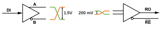
Figure 1, Working Principle of RS-485 Chip
To eliminate signal reflections in communication cables, twisted pairs are generally used to avoid interference. For longer connections, the common practice is to connect terminal resistors at both the beginning and end of the RS-485 bus, as the characteristic impedance of most twisted pair cables is around 120Ω.
Working Modes of RS-485
Taking the A DI ADM3061EARZ as an example, half-duplex RS-485 connections support multiple receivers and transmitters on the same signal loop, but ensure that only one transmitter operates at a time. This can be achieved by controlling the RE (receiver enable) and DE (transmitter enable) pins. Half-duplex RS-485 can transmit data bidirectionally, but only one direction can transmit signals at any given time.
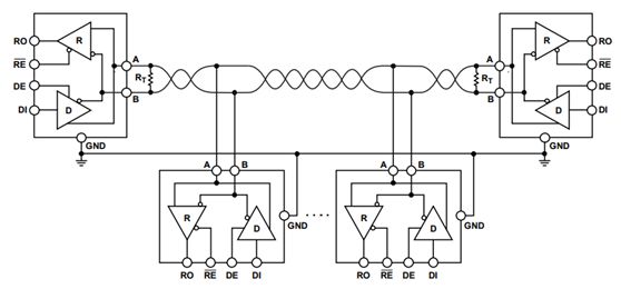
Figure 2, Working Mode of RS-485 Transceiver
For more information about RS485 transceivers, please refer to the detailed information on the Digi-Key official website.
How to Connect RS-485
To avoid signal reflections, the stub length in multiple RS-485 connections should be as short as possible. Also, other connection types, such as star connections, should be avoided.
Note:Theoretically, the stub length should be less than 1/4 wavelength (the wavelength corresponding to the transmission frequency), and in practical applications, the shorter the better.
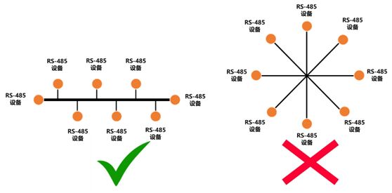
Figure 3, Correct Connection of RS-485
The maximum number of nodes that can be connected is determined by the input impedance of the RS-485 receiver. The standard RS-485 receiver has an input impedance greater than 12K ohms and can drive up to 32 loads. The greater the input resistance, the more loads can be driven. For example, the ADM3061EARZ has an input impedance of 48K ohms and can drive up to 128 loads.
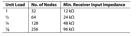
Figure 4, Input Impedance and Load Quantity of RS-485 Receiver
EMC Electromagnetic Interference Risks Faced by RS-485
For the EMC electromagnetic interference of RS-485, the following three situations need to be considered for electrostatic protection:
“Electrostatic Protection ESD:
Cause of interference: Interference caused by static electricity
Path of interference: Finger touch
Corresponding standard: IEC 61000-4-2
Typical interference waveform: Contact discharge ±8 kV, ESD pulse 4mJ, ESD waveform (contact discharge 8kV)
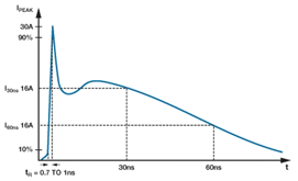
Figure 5, Typical Interference Waveform of Electrostatic Interference
“Electrical Fast Transient Burst Protection EFT:
Cause of interference: Interference caused by fast switching, such as cutting off inductive loads, relay contact bounce, etc.
Path of interference: High-frequency noise coupled to the communication port through various paths
Corresponding standard: IEC 61000-4-4
Typical interference waveform: Port voltage 2 kV, single EFT pulse energy 4mJ, EFT 50Ω load waveform 2kV
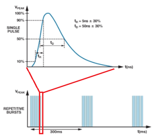
Figure 6, Typical Interference Waveform of Electrical Fast Transient Burst
“Surge” Protection
Cause of interference: Interference caused by switching or lightning transients
Path of interference: Various paths coupled to the communication port
Corresponding standard: IEC 61000-4-5
Typical interference waveform: Surge pulse energy can reach 90J, surge 1.2/50µs waveform
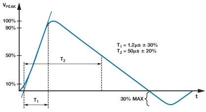
Figure 7, Typical Interference Waveform of Surge Voltage
EMC Electromagnetic Interference Solutions for RS-485
TVS Diode Protection
How to connect: The TVS diode is connected between the line that needs protection and ground, providing overvoltage protection.
How it works: When a transient voltage greater than the breakdown voltage of the TVS occurs, the resistance of the TVS decreases, and energy flows from the TVS diode to ground (<1 ns). After the transient event, the TVS diode automatically resets to a low resistance state, allowing the system to resume normal operation.
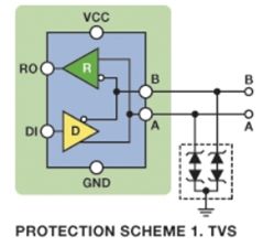
Figure 8, TVS Protection Circuit
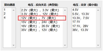
TVS Diode Asymmetric Breakdown Voltage: The RS485 chip needs to ensure operation within the common mode range of +12 V to -7 V. Therefore, the requirement for the TVS diode is also an asymmetric breakdown voltage. For example, the CDSOT23-SM712 has unique characteristics with asymmetric breakdown voltages of +13.3V and -7.5V.
If you need more information about asymmetric TVS diodes, please refer to the relevant information on the Digi-Key website regarding the selection of asymmetric TVS diodes, where you can choose based on parameters, selecting the “12V (maximum), 7V (minimum)” item to find TVS diodes designed for RS485.
Selecting TVS for RS485 Design
TVS diodes provide good protection against EFT and ESD. The energy of surges is typically three to four orders of magnitude higher than that of ESD and EFT, but TVS diodes may not necessarily be able to dissipate surge energy effectively; more complex protection solutions may be needed in this case.
Transient Voltage Suppressor Unit (TBU)
How to connect: The TBU is connected in series with the line that needs protection, providing overcurrent protection, and is used in conjunction with the TVS diode.
How it works: When overcurrent occurs, the TVS works in breakdown state due to the transient voltage, and the resistance of the TBU increases, causing the current to rise to a preset limit level. At this time, the TBU will disconnect the protected circuit from the surge within less than 1µs, allowing only a very small current to pass through the protected circuit (<1mA). After the transient event, the TBU automatically resets to a low resistance state, allowing the system to resume normal operation. A typical TBU is the Bourns TBU-CA065-200-WH.
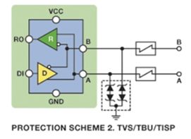
Figure 10, TBU Protection Circuit
Surge Suppression Dedicated Chip
A single device often provides limited protection, so for high-demand applications, multiple devices are often required to work together.
You can visit the Digi-Key website for information on surge suppression ICs and select relevant devices. The Digi-Key website offers a wealth of parameter options for selection; the “external switch” in the figure refers to an additional switch (such as a MOSFET) that needs to be added externally, while this chip generally plays a control role. The “internal switch” refers to the switch of the protection circuit that is built into the chip.
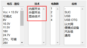
Figure 11, Surge Suppression Dedicated Chip Selection Parameters
Conclusion
Despite being used for many years, RS-485, with its excellent ability to resist common mode noise, is suitable for long-distance signal transmission and remains widely used in industrial environments. We need to choose appropriate EMC solutions based on the complex electromagnetic environment faced by RS-485 to prevent EMI risks during RS-485 applications.
For more technical materials related to RS-485 design, you can search the following articles on digikey.com.cn:
-
Why Use RS-485 for Long-Distance Wired Communication?
-
Implementing Reliable Industrial Connections Using RS-485 and Current Loop Interfaces
-
Options and Solutions for Partitioning Isolated Power in Isolated RS-485 Nodes

Important Notice
The annual technology event is about to begin, and manufacturers are welcome to register for participation! ELEXCON2019 Shenzhen International Electronics Exhibition will be held from December 19-21, 2019, at the Shenzhen Convention and Exhibition Center. ELEXCON2019 will feature several major sections, including electronics, embedded systems, IoT, automotive smart technology and new energy exhibitions, with the theme “Internet of Things in China, Intelligent Future,” showcasing new technologies and products in the fields of 5G, artificial intelligence, IoT, automotive smart technology, and new energy from components, embedded technology to system solutions.
About Electronic Innovation Network
The Electronic Innovation Network timely publishes the latest global semiconductor industry information related to innovative design, updates from semiconductor suppliers, exhibition and seminar information, technical trend information, and interviews with industry figures. Follow our public account for more information.