Introduction
The PLC is known as the “nerve center” of modern factories; however, its workflow consists of only three steps: input sampling, program execution, and output refreshing.
Yet it is the subtle differences in these three steps that create a gap between novices and experienced engineers, causing 90% of engineers to hesitate.
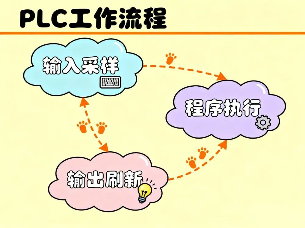
1. Input Sampling: Capturing Real-Time Conditions
All PLCs, whether from internationally renowned brands like Siemens or excellent domestic PLCs, repeat the cycle of input sampling, program execution, and output refreshing every day. The first step is input sampling, which is akin to a photographer capturing a snapshot of the “real-time” conditions on site. The PLC quickly reads the status of various input devices such as buttons, photoelectric sensors, and encoders, storing this “real-time” information in the input image register.
For example, in an automated production line, there are many photoelectric sensors used to detect the position of products. When a product passes by a photoelectric sensor, the sensor transmits the detected signal to the PLC.
During the input sampling phase, the PLC reads the status of all these photoelectric sensors at once, such as which positions have products passing through and which do not. As long as the external wiring is secure and reliable, this step usually proceeds without major issues, successfully completing 99% of the time.
It is similar to a photographer being able to take clear photos as long as the camera and shooting environment are stable. However, if the external wiring is loose or damaged, it may lead to unstable signal transmission, just like a dirty camera lens or improper focus can result in blurry photos, affecting subsequent judgments.
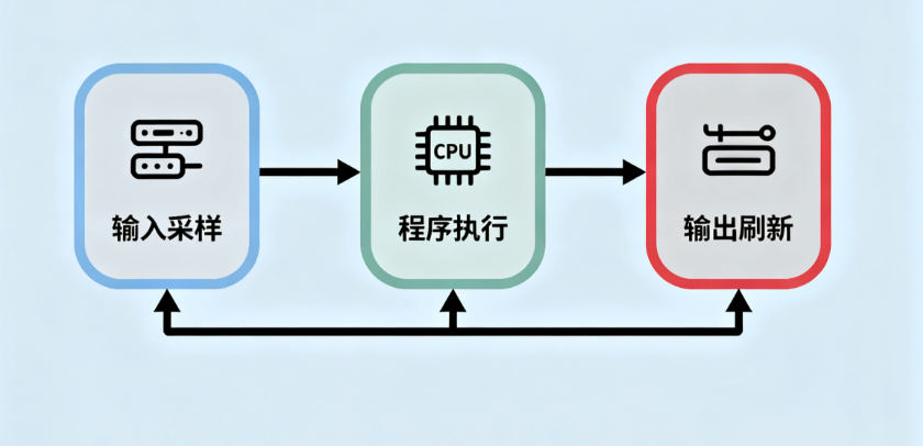
2. Program Execution: Running Logic According to the “Script”
Once input sampling is complete, the process moves to the program execution phase. In this step, the PLC executes the logic line by line according to the ladder diagram, storing the results temporarily in the output image register. This is where the real “pitfall” of the entire PLC workflow lies.
The ladder diagram is a commonly used graphical programming language in PLC programming, resembling a carefully arranged script that dictates how the PLC should respond in various situations. The PLC strictly follows the logical sequence of the ladder diagram, executing instructions line by line. However, if there are excessive long delays or recursive calls in the program, it can lead to significant problems.
For instance, in a system controlling a servo motor, if an unnecessary long delay instruction is inadvertently added to the program, the originally normal scanning cycle may extend from 10 ms to 200 ms.
Servo motors have a very high response speed requirement for control signals, and a significant extension of the scanning cycle is akin to a person who normally walks steadily suddenly being asked to slow down drastically, resulting in unsteady walking; similarly, the servo motor may exhibit “hunting” behavior, failing to operate normally and stably.
Another example is recursive calls; if inappropriate recursion occurs in the program, it may lead to an infinite loop, like a person continuously walking in circles without making progress, ultimately causing the entire system to crash.
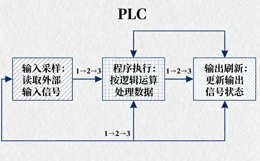
3. Output Refresh: Decisively Pushing Actions
After the program execution phase, we arrive at the output refresh phase. In this stage, the PLC pushes the results temporarily stored in the output image register to output devices such as relays and solenoid valves all at once, executing actions decisively. This is akin to a chef finishing a dish according to a recipe and then serving it all at once to the dining table.
Under normal circumstances, the output refresh can accurately convert the PLC’s processing results into actual device actions. However, if the output module malfunctions at this time, it may create the illusion of “the program has a signal, but the coil does not act.”
For example, in a system controlling the opening and closing of a solenoid valve, the PLC program has correctly sent the signal to open the solenoid valve, and the corresponding result is already in the output image register, but during the output refresh, due to a fault in the solenoid valve module, the solenoid valve does not open as required by the program, making it seem as if the program is ineffective, while the actual issue lies with the output module.
To help remember the PLC workflow, there is a mnemonic: “Sample in one breath, execute one line, refresh in one go.” At the same time, the scanning cycle is also an important indicator, equal to the sum of sampling time, execution time, and refresh time. Under normal circumstances, the scanning cycle generally ranges from 5 to 20 ms.
If the scanning cycle exceeds 50 ms, it indicates that there may be issues with the program, necessitating optimization or splitting the program into multiple segments for processing, similar to how a lengthy movie with a slow pace may feel dragged out to the audience, requiring editing and optimization to make the pace tighter.
Although the PLC workflow consists of only three simple steps, each step contains rich knowledge and potential issues. Only by deeply understanding these three steps can engineers better write and debug PLC programs, allowing the PLC to play its maximum role in industrial automation and avoid being blocked by these seemingly simple steps.
We welcome everyone to leave comments and engage in discussions!