Introduction: The intelligent vehicle system designed in this paper uses a CMOS camera to detect track information, collects grayscale images of the track, generates a binarized image array using a dynamic threshold algorithm, and extracts black guiding lines for track recognition. It detects the real-time speed of the model car using a photoelectric encoder and adjusts the speed of the left and right motors using a PID control algorithm to achieve closed-loop control of the vehicle’s speed and direction. To improve the speed and stability of the model car, extensive hardware and software testing was conducted using debugging tools such as C# and MFC. Experimental results indicate that the system design is indeed feasible.
School: University of Science and Technology Beijing Team Name: Intelligent Vision Group of University of Science and Technology BeijingParticipants: Fan Yiming Pan Yihan Chen Yunqing Instructor: Ma Fei
Introduction
With the development of information technology, the electronic modules of cars are becoming increasingly numerous, and the field of intelligent cars has received significant attention. Commissioned by the Department of Higher Education of the Ministry of Education (Document No. [2005] 201 from the Department of Higher Education), the National College Student Intelligent Car Competition is organized by the Teaching Guidance Subcommittee for Automation Majors in Higher Education, covering multiple interdisciplinary fields such as control, pattern recognition, sensing technology, electronics, electrical engineering, computer science, and mechanics.
Participants must use the race model designated and procured by the competition secretariat, independently adopt a 32-bit microcontroller as the core control unit, and conceive their control scheme and system design, including sensor signal acquisition and processing, control algorithms and execution, motor driving, and steering servo control, to complete the design and debugging of the intelligent car project and participate in the on-site competition at the designated date and location. The ranking of the participating teams is determined primarily by the time taken to successfully complete the track competition on-site, with scores for technical solutions and project quality as supplementary factors.
This year’s National College Student Intelligent Car Competition consists of speed and creativity competitions, with speed competitions divided into eight categories: basic four-wheel group, energy-saving beacon group, intelligent vision group, electromagnetic off-road group, two-car relay group, omnidirectional movement group, single-car pulling group, and specialized basic group, with our team participating in the intelligent vision group competition. According to official regulations, C-type race models must be used, and designated NXP series microcontrollers must be utilized to complete the design for this competition.
This technical report mainly includes mechanical systems, hardware systems, software systems, etc., detailing our design scheme, specifically in the design of hardware circuits and some ideas for control algorithms, hoping to communicate and exchange ideas with students from other schools for further improvement.
Chapter 1 Scheme Design
1.1 System Overview
The overall structure of the camera car system is shown in the figure. The microprocessor collects the hardware binarized signals from the analog CMOS camera to obtain the track edge information; it analyzes bridge information by collecting gyroscope data; and it obtains the speed data of the car by counting the pulses from the photoelectric encoder on the wheel speed. The microprocessor processes the images and performs PID control on the angle and speed, ultimately outputting PWM waves to drive the motors and servos.
Chapter 2 Intelligent Vehicle Mechanics
In accordance with this year’s committee’s regulations and the rules for the intelligent vision group competition, a new C model must be used to complete the tasks. Therefore, a reasonable plan is needed to complete the tasks. At the beginning of the competition preparations, we conducted a detailed system analysis of the car model. However, due to the low precision of the new C-type model, we tried to modify the model within the allowable range of the rules to improve the overall precision of the model to enhance the stability of the vehicle’s movement. This chapter will mainly introduce the mechanical structure and adjustment scheme of the intelligent car model.
2.1 Vehicle Mechanical Scheme
According to the requirements of the 16th Intelligent Car Competition rules for the intelligent vision group, we chose the new C model to complete the tasks.
2.2 Four-Wheel Model Mechanical Modeling
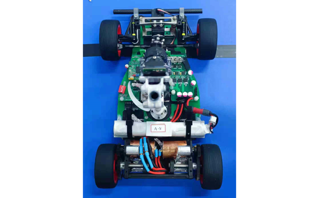
The four-wheel race model for this competition is provided by Dongguan Bosi Electronic Digital Technology Co., Ltd. The appearance of the model is shown in Figure 2.1:
2.2.1 Adjustment of the Front Wheel Angle of the Four-Wheel Model
The rear axle of the four-wheel model is fixed, and there are no major changes to the rear axle. During the debugging process, we found that the front wheels significantly affect the operation of the model, and due to the large gap between the front wheel axle and the wheel, it greatly influences the steering center at high speeds, leading to understeering of the model car during high-speed turns. However, this part is strictly prohibited from modification in the rules, so we adjusted the installation angle of the front wheels to reduce the load on the steering servo as much as possible.
The purpose of the front wheel positioning is to ensure the stability of the car’s straight-line movement, ease of steering, and reduce tire wear. The front wheels are steering wheels, and their installation position is determined by four adjustable parameters: the inclination of the main pin, the rear inclination of the main pin, the outward inclination of the front wheel, and the front wheel toe-in, achieving the positional relationship among the steering wheel, main pin, and front axle on the chassis.
In actual debugging, we found that appropriately increasing the inward inclination angle can increase the contact area between the wheels and the ground during turns, thereby increasing the friction between the vehicle and the ground, making the car more agile in steering and reducing the understeering caused by insufficient friction. Moreover, the model designed by our intelligent vision group has a higher center of gravity and is more forward compared to previous models, so we made some adjustments to the rear inclination of the main pin.
2.2.2 Adjustment of Chassis Height
Under the premise of ensuring smooth passage over ramps, the chassis should be lowered as much as possible to reduce the center of gravity of the model car overall, making the model car more stable and high-speed during turns. However, a chassis that is too low may cause scraping against the chassis when going up ramps, affecting the normal operation of the model.
2.2.3 Gear Meshing and Encoder Installation
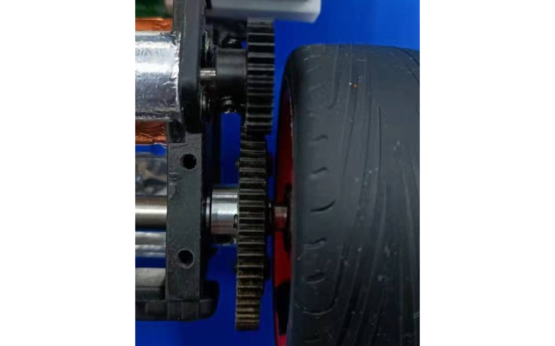
Considering that the intelligent vision group requires the vehicle to stop, we have high requirements for the gear meshing of the car. Poor meshing can greatly impact the normal operation and stopping of the vehicle. To obtain a more accurate return value of the motor speed, we installed the same encoder as the previous model on this car model. Ultimately, we considered both reading accuracy and center of gravity distribution, using gears for installation to keep the transmission gear axis as parallel as possible, ensuring that the transmission part is easy and smooth, with no excessive noise, tooth skipping, or data loss, as shown in Figure 2.2.
2.2.4 Servo Installation Structure
Considering the convenience of mainboard installation and the steering performance of the model, we made significant adjustments to the servo installation structure. The steering of the race model is achieved through the servo driving the left and right tie rods. The rotation speed and power of the servo are fixed; to accelerate the response speed of the steering mechanism, the only way is to optimize the servo installation position and the length of its torque extension rod. Since power is a function of speed and torque, overly pursuing speed will inevitably sacrifice torque, and too little torque will also cause sluggish steering. Therefore, during the design, it is necessary to comprehensively consider the relationship between the response speed of the steering mechanism and the torque of the servo, optimizing to achieve the best steering effect. Using actual parameters and calculations, we derived a set of parameters and structures that can work stably and efficiently.
Finally, we designed a servo linkage (steering tie rod) that considers the relationship between speed and torque, and simplified the installation method based on the specific structure of the model car chassis to achieve the expected goal.
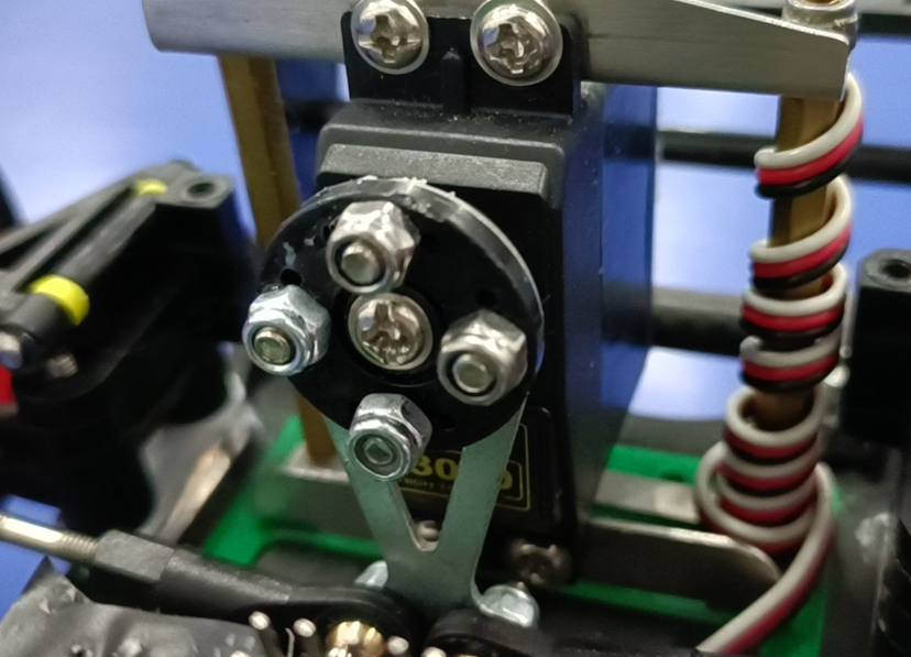
Regarding the installation method of the servo, our laboratory has two mainstream methods: upright installation and inverted installation, and our servo installation is shown in Figure 2.3.
2.2.5 Servo Angle Analysis
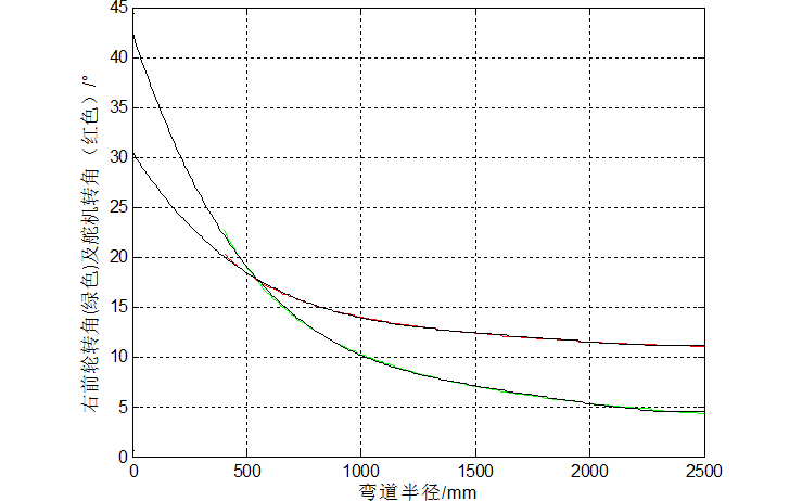
The steering motion of the model is mainly achieved through the servo and the front wheels, so analyzing the relationship between the servo and the front wheel steering is particularly important. Based on mathematical modeling and analysis conducted using MATLAB, the following results were obtained.
The relationship between the right front wheel angle (green) and the servo angle (red) concerning the turning radius is shown in Figure 2.4.
The relationship between the servo angle and the (right) front wheel angle is shown in Figure 2.5.
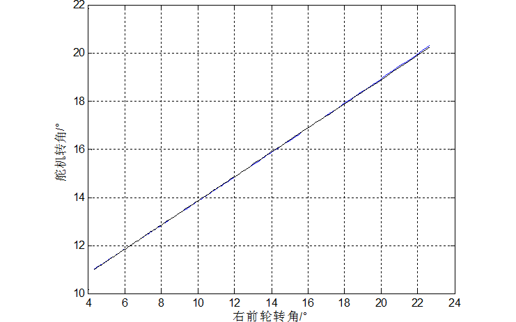
From the above two figures, we conclude:
-
The range of change in the servo angle is small, yet the change in the turning radius can be significant, thus multi-level control is particularly important.
-
The smaller the front wheel angle, the more pronounced the change in turning radius with the change in angle, indicating that a small steering angle has a more significant effect on the radius, hence the mechanical fixation from the front axle to the servo linkage must be secure to minimize play.
-
The servo angle changes linearly concerning the front wheel angle, which conceptually facilitates obtaining the desired front wheel angle through changing the servo angle. By altering the toe-in, a new relationship between the right front wheel angle (green) and the servo angle (red) concerning the turning radius is obtained, as shown in Figure 2.6. By comparing with Figure 2.4, we derive the influence of the two front wheel schemes on the steering angle, thus selecting the appropriate scheme.
Figure 2.6 illustrates this.
2.2.6 Camera Installation
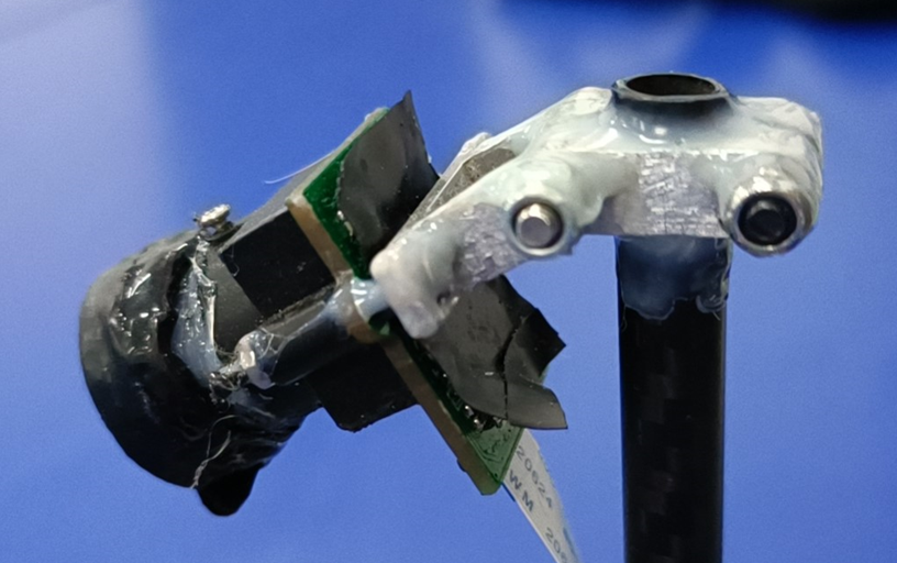
To lower the overall center of gravity of the vehicle, it is crucial to strictly control the installation position and weight of the CMOS camera. We designed a lightweight aluminum alloy clamping component and used carbon fiber tubes as the main mast for installing the CMOS, achieving the best stiffness-to-weight ratio, resulting in a device with high positioning accuracy and rigidity, facilitating easy disassembly and maintenance of the camera, and providing rapid support capabilities on the competition field. The camera installation is shown in Figure 2.7.
2.2.7 Using Mini Camera for Task Design
In the design of fixing the mini camera, since the mini camera needs to rotate, we used a small metal servo to drive the mini camera’s rotation, which reduces volume and weight. The fixing method is the same as that of the CMOS camera, and this scheme has the advantages of high stability and robustness. After practical testing, the feasibility of this scheme has been validated.
Chapter 3 Circuit Design Explanation
3.1 Hardware Scheme Design
We primarily consider the overall design of hardware from aspects of system stability, reliability, efficiency, practicality, and simplicity. From the initial scheme setting to the final scheme confirmation, we went through various discussions and significant changes to arrive at the following hardware scheme.
Reliability and stability are the maximum prerequisites for a system to fulfill its preset functions. During the design of schematics and PCBs, we considered the electrical characteristics of each functional module and the coupling effects between them. We implemented electromagnetic shielding for modules that are easily interfered with, while other parts were grounded, filtered, and isolated between analog and digital circuits.
Efficiency and practicality mean that each module of the system can fully and perfectly realize its corresponding functions. The following two points illustrate this:
-
There are generally three methods for extracting video signals: on-chip AD conversion, 8-bit parallel AD based on TLC5510, and hardware binarization. The first method converts continuous analog video signals into digital signals for storage through on-chip AD conversion. The second method directly converts video signals into parallel digital signals through external AD chips, while the processing chip only needs to read the stored data through ordinary IO; the former does not require external circuits but wastes system time, placing a significant burden on processing chips with low main frequencies. Although the latter has high precision, it wastes excessive hardware resources. Hardware binarization captures the video signal’s transition edges through comparators, which not only reduces acquisition time but also saves hardware resources and storage space. However, hardware binarization has poor flexibility; when facing complex lighting environments, fixed thresholds cannot dynamically adjust local thresholds as needed, making it unable to resolve unevenly distributed lighting on track environments. Digital signals occupy computational resources, but on the condition that the chip’s computational capacity is satisfied, complex algorithms can handle uneven lighting on track environments, demonstrating stronger adaptability.
-
For motor driving, due to the high driving performance requirements of the new C model motor, we designed a driver composed of separate driving chips, which can instantaneously drive currents up to several tens of amps.
Simplicity means that after satisfying reliability and efficiency requirements, to reduce the load on the model and lower the center of gravity of the model car, the circuit design should be as simple as possible, minimizing the number of components used and reducing the circuit board area to make the circuit portion lightweight and easy to install. After completing the schematic design, we focused on the layout of the PCB, optimizing the circuit routing, neatly arranging components, ultimately achieving a concise circuit board.
3.2 Sensor Selection
3.2.1 Camera Selection
-
COMS and CCD
CCD cameras have the advantages of high contrast and good dynamic characteristics, but they require operation at 12V voltage, which is too power-consuming for the entire system, and the CCD is bulky and heavy, raising the center of gravity of the vehicle, which is extremely detrimental to the small car’s performance at high speeds.
In contrast, COMS cameras are small, lightweight, low-power, and have good dynamic image characteristics. Since the small car does not have high requirements for image clarity and resolution, we chose the COMS camera.
When selecting the camera, we mainly considered the following parameters:
-
Chip size -
Automatic gain -
Resolution -
Minimum illumination -
Signal-to-noise ratio -
Standard power -
Scanning method
Among these, the chip size primarily affects the field of view, while the scanning method can be either progressive scan or interlaced scan, with OV5116 being an example of interlaced scan.
Market cameras mainly fall into two categories: digital and analog. Digital cameras include OV7620, OV6620, OV7670, OV7725, while analog cameras include OV5116, BF3003, MT9V136. Most cameras support SCCB communication, facilitating good interaction between the microcontroller and the camera.
The intelligent car’s camera does not have high resolution requirements but has very high dynamic characteristics requirements, especially when the small car is entering or exiting turns at high speed, where the image changes significantly, thus requiring high automatic gain from the camera. Generally, when the camera image experiences abrupt changes, the light-sensitive chip itself has a certain adaptation time, and the shorter this time, the better.
We tested OV5116, MT9V022, OV7725, BF3003, MT9V136, and PC1030N cameras; the last four are all color cameras. After hardware binarization, they can extract effective information similar to that obtained from black-and-white digital cameras. After comparison, although the last four cameras have better image quality and dynamic performance, in elements such as sharp turns and loops, automatic exposure leads to inaccurate track information. In the application of intelligent vehicles, MT9V022 is sufficient to meet the requirements, so we ultimately chose the MT9V022 digital camera.
3.2.2 Gyroscope Selection
This year’s competition does not restrict the model of the gyroscope, and after selection, we finally determined to use the L3G4200D gyroscope.
The L3G4200D product from ST adopts a sensing structure to detect motion along three orthogonal axes, functioning as a 3-axis digital gyroscope. The L3G4200D shares a sensing structure among the three axes, eliminating signal interference between axes and preventing output signals from being affected by interfering signals.
3.2.3 Encoder Selection
To implement closed-loop control, we added encoders to the car model. After considering mechanical and circuit performance, we ultimately selected the ABI Mini incremental rotary encoder.
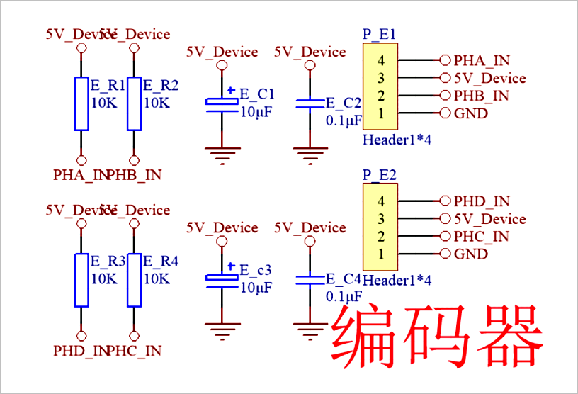
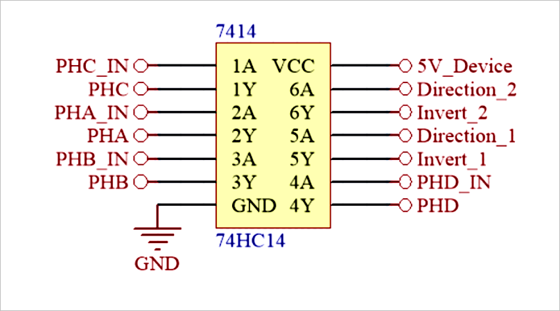
Compared to other components, using encoders can enhance circuit completeness and signal accuracy. Encoders have low power consumption, are lightweight, shock-resistant, vibration-resistant, have high precision, long lifespan, and are highly practical. The encoder has no pull-up resistor internally, so pull-up resistors need to be designed on the encoder interface. To ensure waveform stability, a 74HC14 inverter is used for isolation on the main control board. The microprocessor itself has orthogonal decoding functions, so no peripheral counting auxiliary devices are needed; just connect the interface to the corresponding interface on the microcontroller. The interfaces are shown in Figures 3.1 and 3.2.
3.3 Circuit Module Implementation
3.3.1 Power Management Module
First, let’s understand the characteristics of different power supplies. Power supplies can be divided into switching power supplies and linear power supplies. The voltage feedback circuit of linear power supplies operates in a linear state, while switching power supplies refer to the tubes used for voltage adjustment operating in saturation and cutoff regions, i.e., switching states. Linear power supplies generally sample the output voltage and send it to a reference voltage comparator, whose output is fed into the voltage adjustment tube to control the adjustment tube to change its junction voltage according to input variations, thus adjusting the output voltage. In contrast, switching power supplies change the output voltage by altering the on-off time, i.e., the duty cycle of the adjustment tube.
From their main characteristics: Linear power supply technology is mature, with low production costs, achieving high stability with minimal ripple, and no interference and noise associated with switching power supplies. Switching power supplies are efficient, with low loss, and can step down or step up voltage, but they have slightly larger AC ripple.
The power module is extremely important for a control system, as it determines whether the entire system can operate normally. Therefore, an appropriate power module should be selected when designing control systems. The competition rules state that the intelligent car must use the standard model provided by the intelligent car competition, powered by a 7.2V 2000mAh Ni-Cd battery or lithium batteries (two 18650s, 2AH, equipped with a protection board). After multiple comparisons and attempts, we chose to use lithium batteries. The CCD sensor used for path recognition operates at 3.3V. The microcontroller system, gyroscope, and encoder require a 5V power supply, while the servo motor operates within a voltage range of 4V to 6V (to improve the response speed of the servo motor, 7.2V is used). The DC motor can be powered directly by lithium batteries; a voltage regulation circuit diagram for the intelligent car is shown in Figure 3.3.
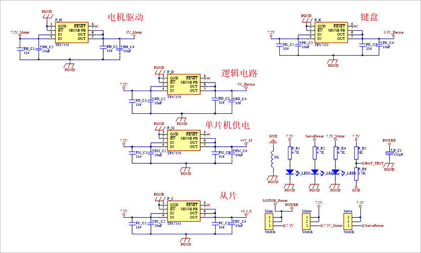
In the power management module, we selected five TPS7350 and two TPS7333 chips, where DCDC5-12 and IR2184S share a 5V power supply, the logic elements and encoder share another 5V power supply, while OpenArt mini and the main microcontroller each use a separate 5V power supply, with other modules sharing a 3.3V power supply. To ensure stable power supply for the camera and meet its operational requirements at high speeds, we added a separate 5V power supply for the camera.
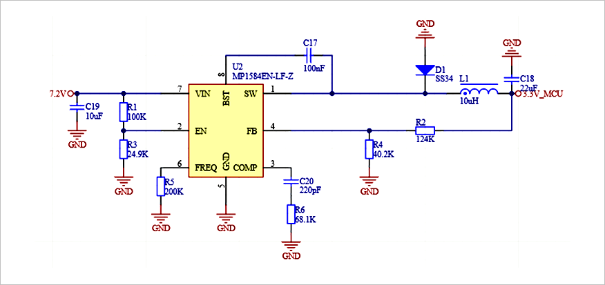
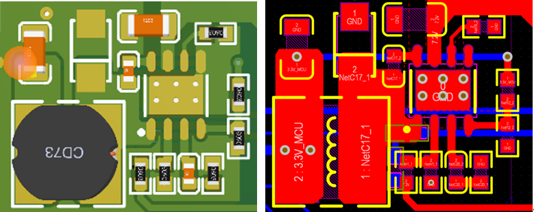
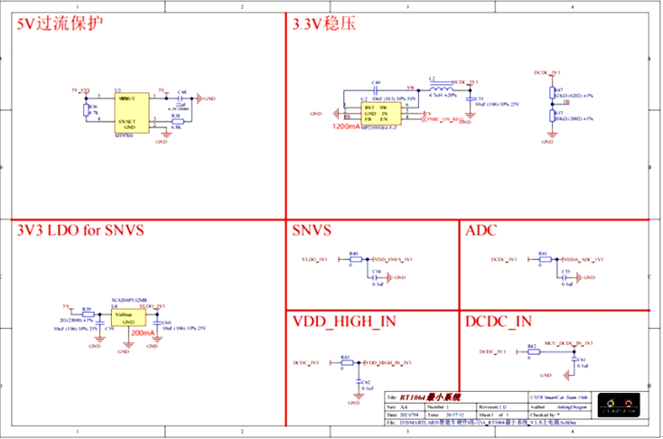
The 16th competition rules stipulate that the microcontroller for the AI vision group must use any model of microcontroller from NXP. After consideration, we decided to use the microprocessor as the main control microcontroller. Initially, we used the TPS7350 as the power supply chip for the microprocessor, but during actual use, we found that the TPS7350 tends to overheat. Considering the relatively high power consumption of the microprocessor, we decided not to use LDO as the power supply chip for the microprocessor minimum system, but instead replaced it with a DC-DC step-down chip. We later tried the AOZ1280CI and MP1584EN chips, and after a period of actual use, we finally confirmed the use of MP1584EN. The schematic and PCB layout are shown below:
3.3.2 Motor Driver Module
Common motor driving methods include two types:
1. Integrated motor driver chips;
2. Using N-channel MOSFETs and dedicated gate driver chips for design. Among the commonly seen integrated H-bridge motor driver chips on the market, the 33886 chip performs exceptionally well, featuring comprehensive overcurrent, undervoltage, and overtemperature protection functions, with an internal MOSFET on-resistance of 120 mΩ and a maximum continuous operating current of 5A. Using integrated chips simplifies circuit design and enhances reliability, but performance is limited. Since the internal resistance of the competition motor is only a few mΩ, while the on-resistance of each MOSFET in the integrated chip is above 120 mΩ, this significantly increases the total resistance of the armature circuit, leading to a substantial drop in the speed of the DC motor and lower efficiency of the driving circuit, preventing the motor from fully exerting its performance.
In contrast, discrete N-channel MOSFETs have extremely low on-resistance, greatly reducing the total resistance of the armature circuit. Additionally, a specially designed gate driving circuit can improve the switching speed of the MOSFETs, allowing for higher modulation frequencies in PWM control, thereby reducing armature current pulsation. Furthermore, dedicated gate driver chips typically have functions such as preventing cross-conduction, hardware dead time, and undervoltage protection, enhancing the reliability of circuit operation.
1. Selection of Dedicated Gate Driver Chips: IR is known as a leader in power semiconductors, so we primarily selected products from IR. Among them, the IR2184 half-bridge driver chip can drive both high-side and low-side N-channel MOSFETs, providing substantial gate driving current and featuring hardware dead time and hardware cross-conduction prevention functions. Using two IR2184 half-bridge driver chips can form a complete H-bridge driving circuit for the DC motor. Due to its comprehensive functions, low cost, and easy procurement, we chose it for our design, as shown in Figure 3.6.
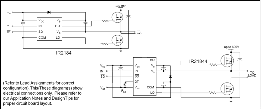
2. Selection of MOSFETs: When selecting MOSFETs, the primary factors considered are voltage rating, on-resistance, and packaging. The power supply for the intelligent car is a battery pack rated at 7.2V, and since the motor may be in regenerative braking mode during operation, the components in the driving section should ideally have a voltage rating of at least twice the power supply voltage, i.e., above 16V. The lower the on-resistance, the better. Larger packages can handle higher power, meaning that under the same on-resistance, larger packages can carry larger currents, but larger packages also have larger gate charges, which can affect switching speed. Common MOSFET packages include TO-220, TO-252, SO-8, etc. The TO-252 package offers higher power while having smaller gate charge. Thus, we ultimately chose the IR company’s TO-252 package LR7843 N-channel MOSFET, with VDSS=55V, RDS(on)=8.0 mΩ, ID=110A.
3. Analysis of Driver Circuit Principles and Component Parameter Determination
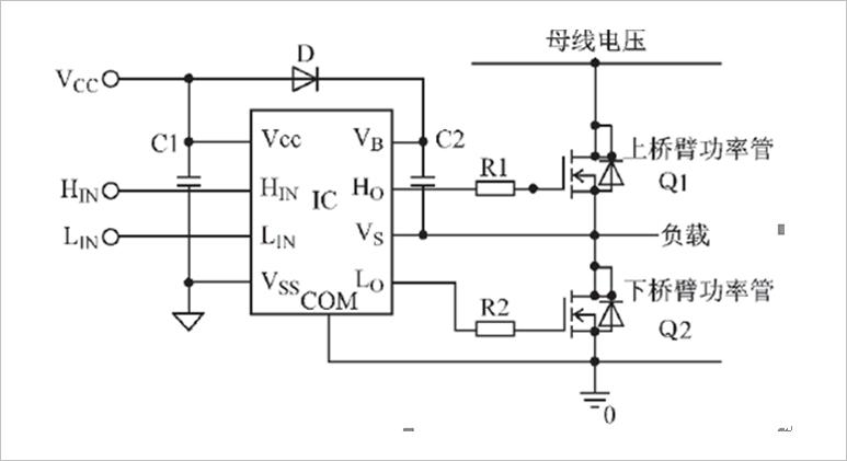
This driver design is relatively easy to understand from a logical signal perspective, but to gain a deeper understanding and better application, a thorough analysis of the circuit and theoretical analysis of the parameters of some peripheral components are required. In Figure 3.8, IC is a high-voltage driver chip driving two half-bridge MOSFETs. Vb and Vs are powered by the high-voltage end; Ho is the high-voltage end driving output; COM is the low-voltage end driving power supply, and Lo is the low-voltage end driving output; Vss is the digital circuit power supply. The upper and lower arms of this half-bridge circuit alternately conduct; whenever the lower arm is turned on, the upper arm is turned off, the potential at the Vs pin is the saturation conduction voltage drop of the lower arm power tube Q2, which is basically close to ground potential. At this time, Vcc charges the bootstrap capacitor C2 via the bootstrap diode D, bringing it close to Vcc voltage. When Q2 turns off, the voltage at the Vs pin will rise; since the voltage across the capacitor cannot change abruptly, the voltage at the Vb pin will approach the sum of the Vs and Vcc voltages, while the voltage between Vb and Vs will still be close to Vcc voltage. When Q2 turns on, C2 acts as a floating voltage source driving Q2, and the charge lost by C2 during the on time of Q2 will be replenished in the next cycle; this bootstrap power supply method utilizes the voltage level at the Vs pin oscillating between high and low to achieve.
Since the bootstrap circuit does not require a floating power supply, it is the cheapest. As shown, the bootstrap circuit charges a capacitor; the voltage on the capacitor fluctuates based on the source voltage of the high-side output transistor. Components D and C2 in Figure 2.6 are crucial devices that must be carefully selected and designed in the IR2184 during pulse width modulation (PWM) applications, and must be calculated and analyzed according to specific rules during circuit experiments to ensure the circuit operates at optimal conditions. Here, D is an essential bootstrap device that should block the high voltage on the DC bus, and the current it withstands is the product of gate charge and switching frequency. To minimize charge loss, a fast-recovery diode with low reverse leakage current should be selected, and all high-voltage parts of the chip are powered from the charge on the bootstrap capacitor C2; to ensure that the high-voltage circuit has sufficient energy supply, the size of C2 should be appropriately selected.
MOSFETs have similar gate characteristics; when turned on, they require sufficient gate charge to be provided to the gate in a very short time. The distributed inductance in the charging path of the bootstrap capacitor affects the charging rate. The narrow conduction time of the lower arm power tube must ensure that the bootstrap capacitor has enough charge to meet the gate charge requirement plus the charge lost due to the steady-state leakage current of the power device. Therefore, considering the minimum value of the narrow conduction time, the bootstrap capacitor should be sufficiently small; in summary, when selecting the size of the bootstrap capacitor, it should neither be too large to affect the driving performance of narrow pulses nor too small to affect the driving requirements of wide pulses, and should be selected and estimated based on the operating frequency, switching speed, and gate characteristics of the power device.
3.3.3 Video Processing Module
Our intelligent model car’s automatic control system uses a black-and-white full television signal format CMOS camera to collect track information. The video signal from the camera contains not only image signals but also line sync signals, line blanking signals, field sync signals, field blanking signals, and digital signals. Therefore, to capture the video signal, it is necessary to set parameters for the digital camera through SCCB.
3.3.4 OpenArt Mini
For the AI vision group, to accomplish tasks such as recognizing QR codes, numbers, fruits, and animals, the OpenArt Mini is indispensable. We purchased a finished camera from Zhufei Technology and communicated the recognized information with the main microcontroller through serial port to execute corresponding tasks.
3.3.5 Interfaces and External Modules
For the minimum system of the microcontroller, the gyroscope board, video module, and OpenArt Mini, we designed external interfaces on the mainboard for connection.
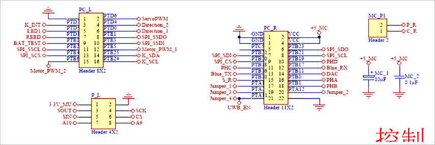
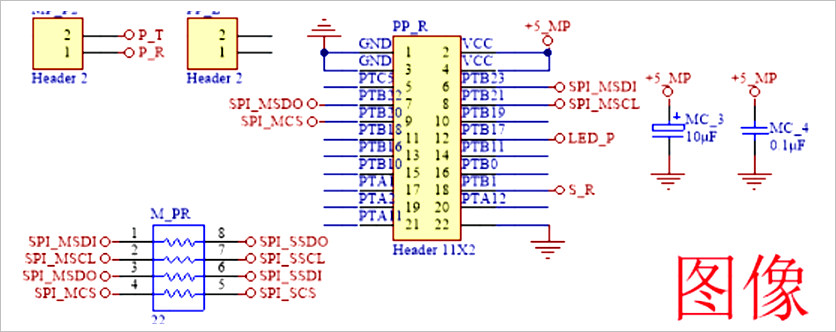
Our minimum system schematic refers to the minimum system schematic of the microprocessor from Longqiu Company and NXP Company. We modified the core power supply scheme and shielded unused pins. On the software side, we used the open-source library provided by Longqiu Company.
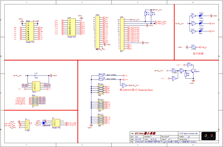
During the debugging process, we needed to understand and monitor some vehicle operating states in real-time, such as sensor status and servo angles. During debugging, we used an OLED display to show these parameters, allowing us to monitor the vehicle’s status in real-time, which greatly facilitated vehicle debugging.
Chapter 4 Intelligent Vehicle Control Software
Efficient software programs are the foundation for intelligent vehicles to automatically and rapidly seek lines. Our intelligent vehicle system uses a CMOS camera for track recognition, and image acquisition and correction processing become the core content of the entire software. In terms of steering and speed control for the intelligent vehicle, we employed a classic PID control algorithm with good robustness, combined with theoretical calculations and practical parameter compensation methods to enable the intelligent vehicle to stably and quickly seek lines.
4.1 Extracting and Optimizing the Center Line of the Track
4.1.1 Characteristics of the Original Image
After the microcontroller captures image signals, it needs to process them to extract the main track information. However, due to the presence of cross paths and starting lines, light interference, noise, and unclear images of the distant track, the image quality is significantly compromised. Therefore, it is essential to eliminate interference factors in the software to effectively recognize the track and provide as much track information as possible for decision-making.
The track information we extracted in the image signal processing mainly includes: the positions of the left and right edges of the track, the center position of the track calculated through correction, the planned area of the center point, the amplitude of track changes, and the classification of track types.
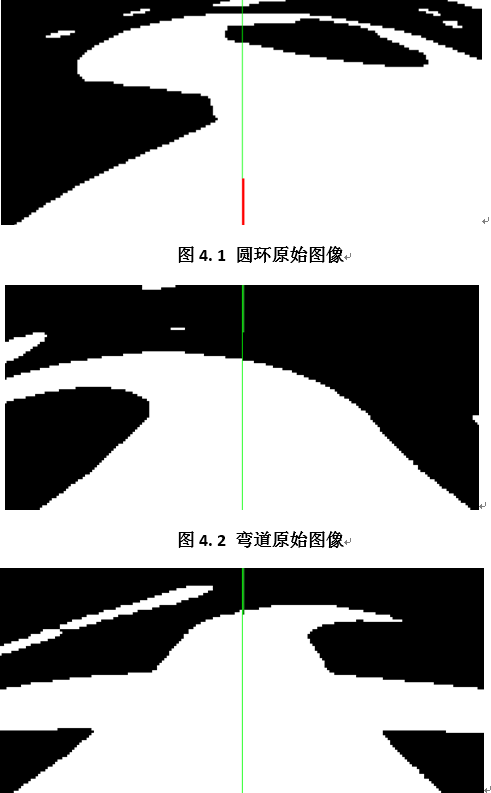
Due to the characteristics of the camera itself, the image produces trapezoidal distortion, making the information seen by the camera unrealistic. Therefore, we measured the track to create a function that restores the real track information. The original image is a two-dimensional data matrix obtained by converting a digital image through an analog circuit, with each element in the matrix corresponding to a pixel point, and the nearer images being larger, with the black line appearing trapezoidal.
The program records the black and white transition points (in the order from right to left) of each line and saves them into two two-dimensional arrays (representing rising and falling edges, respectively). By traversing the rising and falling edges, we can complete the extraction of the track edges.
Typical track images captured by the camera are shown in Figures 4.1 to 4.4.
4.1.2 Edge Extraction of the Track
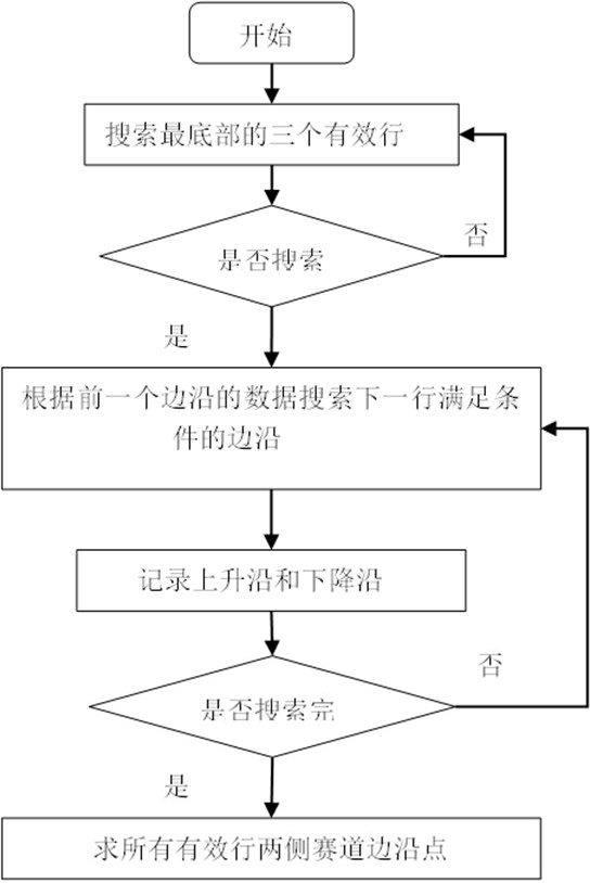
The basic idea of the edge extraction algorithm is as follows:
(1) Directly scan the original image line by line to extract black and white transition points based on a set threshold; (2) The track width has a certain range, and valid track edges are extracted within the determined track width range, which helps filter out interference that is not within the width range; (3) Utilizing the continuity of the track, determine the edge points of the current row based on the positions of the white blocks and edges from the previous row; (4) When seeking edge points, since near images are stable while distant images are unstable, a near-to-far approach is adopted; (5) When entering or exiting a cross, the edge angle can be corrected to effectively filter the cross and fill the line; (6) The chevron element is a part of the track edge with sharp angles. Based on this feature, by calculating the angle of the edge and the area formed by the enveloping of the two inner edges, we can effectively recognize the chevron; to eliminate the interference caused by sudden changes in track direction, we model the chevron as a curve with a certain curvature and perform line filling; (7) Due to the issue of weight distribution, if obstacles are not processed to a certain extent, the control response to distant obstacles will be relatively small, and may only respond when very close to the obstacle, which can easily lead to collisions. To eliminate this influence, we artificially enlarge the area affected by the obstacle using a curved envelope, effectively avoiding the danger of colliding with obstacles.
The program flow of the edge extraction algorithm is shown in Figure 4.5.
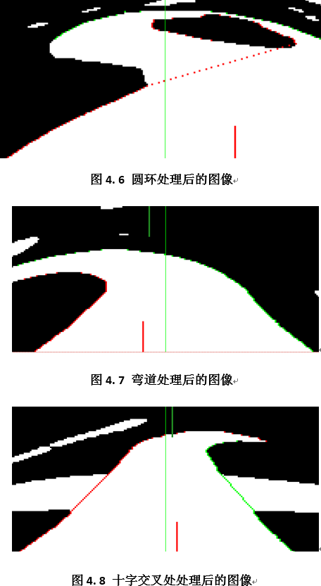
The center of the black line obtained after processing is shown in Figures 4.6 to 4.9.
4.1.3 Image Correction
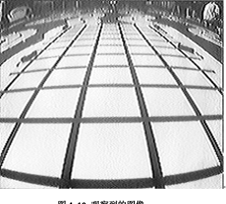
The implementation of image correction is as follows: (1) Adjust the camera position and perspective and fix it; aim the camera at the black and white striped track board, then watch the camera image on a television and photograph it with a camera (see Figure 4.10);
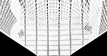
(2) Extract the track portion from the photo, then use MATLAB to write a program to load the image and perform the necessary barrel and perspective transformations, adjusting parameters to generate correction and inverse correction tables;
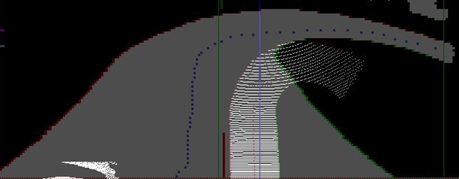
(3) Add the constant table in the microcontroller program, and then perform the corresponding correction and inverse correction transformations. (4) The correction effect observed on the upper computer is as follows:
4.1.4 Central Point Calculation
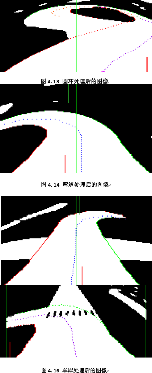
Using the previously extracted edge data of the track to calculate the center: When the total number of edge points on both sides is small, return; if only one side has edge point data, use correction to translate the single side data by half the width of the track along the normal; when a matching edge point can be found on the other side, directly calculate its center as the center point. After calculating the center point, it is smoothed for easier control afterward. The calculated center point effect is as follows:
4.1.5 Processing of Camera Images for Parking
Our strategy is to use the camera to guide the vehicle into the parking space. After the vehicle completes the second half of the track, it first identifies the features of the garage in front of it, determines that the current image is of the garage, finds the starting and ending points for the parking line, and then calls the line-filling function to fill a quarter-circle arc with a radius equal to the width of the track in the image correction domain, processing the left and right boundary points uniformly, resulting in the image shown above.
4.1.6 Path Selection
Based on experiences from previous competitions and this year’s North China competition, the ability of the racing car to complete the race in the shortest time is closely related to both speed and path. Therefore, how to enable the racing car to complete the race along the most reasonable and efficient path is key to improving average speed. For optimizing the racing path, we completed this from the following three aspects:
1) Increase the length and width of the field of view According to our analysis, when the image collected by the racing car can cover a relatively complete S-turn, the center calculated through the weighted algorithm will be near the center of the field of view, allowing the racing car to quickly pass through the S-turn along a better path; conversely, if the field of view cannot cover a complete S-turn, the racing car will misinterpret it as a regular single-direction turn, significantly slowing down the vehicle’s speed. Therefore, it is necessary to maximize the length and width of the field of view.
The length of the field of view is proportional to the number of image lines that the microcontroller can process. We used an operational amplifier-based analog comparator for image binarization, significantly improving processing speed compared to A/D conversion, greatly increasing the number of image lines processed by the microcontroller to 95 lines (extracting one line every three lines), achieving a field length of over 200 cm. To increase the field width, in addition to increasing the number of image points collected per line, we used a wide-angle lens, effectively increasing the field width.
2) Optimize the weighted algorithm The algorithm for calculating the weighted average of the center of all effective lines can effectively optimize the racing path at low speeds, but when the racing speed reaches a certain level, due to side slip during turns, the path is not optimal. Additionally, due to uneven image distribution, two-thirds of the lines are distributed within the 40 cm range in front of the vehicle, causing the calculated weighted average to be significantly influenced by the images close to the vehicle. Therefore, the overall image weighting algorithm’s effect on path optimization at high speeds is not very noticeable.
To address this issue, we adjusted the number of image lines participating in the weighted calculation and their weights, reducing the number of image lines and weights from the 50 cm range in front of the vehicle while increasing the weight of images from the front of the field of view. After extensive debugging, we obtained a suitable set of parameters that can effectively optimize the racing path at high speeds.
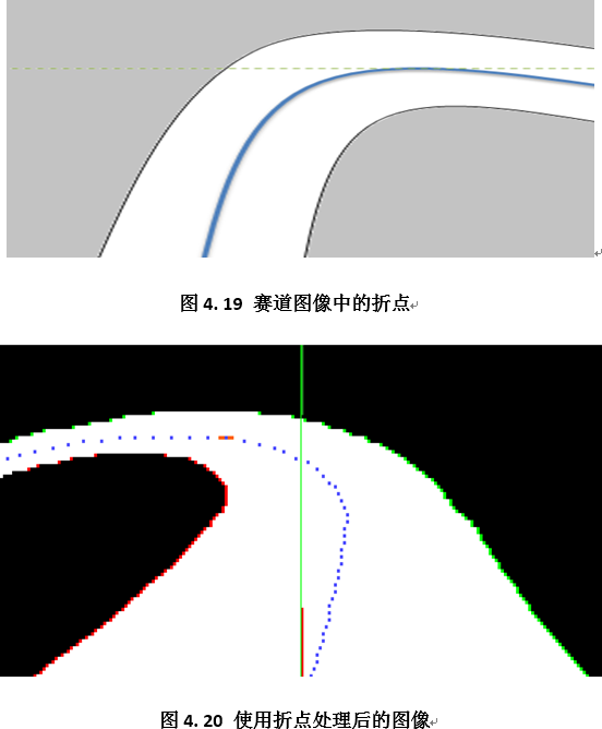
3) Process unreasonable center points For the center line obtained from the corrected image data, when inverse correcting to the original image, there may be multiple center points in a single line. Usually, this situation occurs in the distant field of view, but since we increased the weight of images in front of the field of view, these center points significantly influence the weight, leading to the model car easily losing wheels or even going off track. To solve this problem, we used mathematical methods to find the inflection points of the center line, processing the center points after the inflection points separately to prevent the model car from losing wheels.
4.2 Principle of Inflection Point Calculation
The inflection point refers to the extreme value point in mathematics, where the first derivative is zero; however, a point where the first derivative is zero is not necessarily an extreme value point; to determine whether it is an extreme value point, the second derivative must also be considered. In the discrete data of the image, the calculation formula for extreme value points is as follows:
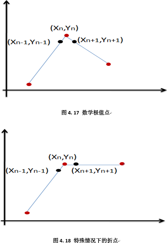
However, this formula has some issues in Figure 4.18; for the point (Xn, Yn), since it is zero, it will not be judged as an extreme value point. However, we believe that such points can also reflect the characteristics of the image, so we modified the above formula to obtain a new method for calculating inflection points:
Extreme value points are relative to a specific coordinate axis; with slight modifications to the above formula, we can obtain the calculation formula for extreme value points on another coordinate axis:
By combining extreme value points from both directions, we can not only filter out unreasonable center points but also achieve a rough judgment of track types.
4.3 Introduction to PID Control Algorithm
[PID Algorithm, Omitted]
4.4 PID Control Algorithm for Steering Servo
For the closed-loop control of the servo, we adopted a position-based PID control algorithm. Based on past technical materials and practical testing, we established a linear relationship between the weighted average of the black line center from each image and the reference angle value for the servo PID.
During tests at lower speeds (below 2 m/s), within a certain range of minimal deviation from the black line, we set Kp to zero directly. In the range of minimal deviation from the black line, we reduced Kp to half of its original value, while maintaining the original value of Kp in cases of larger deviations. The actual effect achieved on tracks with many turns and short straight sections was smooth turning of the vehicle, with the vehicle generally maintaining straight acceleration on straight sections and minimal lateral shaking.
When increasing the speed to high speeds (above 2.5 m/s), we found that the vehicle’s body shakes significantly on straight sections, especially on long straight sections. The reasons are, we believe, first that the wheel axles themselves are loose and that the steering mechanism’s left and right steering performance may be asymmetric, requiring design improvement. Second, the PID control we wrote for the servo is not fine-tuned enough, lacking dynamic adaptability. In transitioning from turns to straight sections, since the small car essentially operates as a following system, the accumulated deviation from the integral term during turns is incorrectly applied to the tracking on the straight sections, resulting in inaccurate steering when entering straight sections. Although the car can track the black line on straight sections, steering adjustments often overshoot, causing the vehicle to shake left and right on straight sections, severely affecting overall speed. Additionally, our control of S-turns was overly simplistic, lacking specific handling, which caused the car to follow the S-turn closely without a clear effect of charging into the S-turn; this is due to limited foresight, leading the car to turn based on the image of the S-turn that resembles a regular turn, causing the small car to oscillate left and right along the S-turn, while corresponding speed decreases.
After repeatedly debugging the PID parameters, we found that merely adjusting the PID parameters made it difficult for the car to choose the optimal path when transitioning between S-turns and long straight sections without affecting steering at standard turns. This requires the system to intelligently identify the current track type. Instead of using track memory methods, we adopted the approach of allowing the camera to see further without reducing distant resolution. Finally, under the condition of overclocking the MCU, we captured 210 points per image line, successfully increasing the resolution of the CMOS camera. Despite the limitations of perspective issues affecting distant resolution, the field length (the distance from the farthest to the nearest point in the field of view) reached over 2m, with the farthest foresight reaching 2.20m, sufficient to cover various track types, allowing us to not include algorithms for reliably identifying S-turns, long straight sections, and large turns in our program; instead, we dynamically adjusted PID parameters based on the center position, achieving good control effects.
After extensive testing, the PID adjustment strategy we selected is:
(1) Set the integral term coefficient to zero. We found that in terms of stability and precision, the servo in this following system has a higher demand for dynamic response performance. More importantly, with KI set to zero, by reasonably adjusting Kp, we found that the vehicle can maintain stability without oscillation while driving at high speed in a straight line, making it generally unnecessary to use the KI parameter;
(2) The differential term coefficient KD is set to a fixed value, as the servo requires good dynamic response capability in general tracks;
(3) For Kp, we used a quadratic function curve, where Kp increases in a quadratic relationship with the deviation between the center position and the center value, with specific code in the program as follows: loca_Kp = (loca_error * loca_error)/2 + 1000.
Here, local_error is the deviation between the center position and the center value.
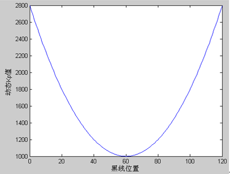
After continuous debugging, we selected a set of PID parameters that achieved relatively ideal steering control effects.
4.5 PID Control Algorithm for Driving Motor
For speed control, we adopted an incremental PID control algorithm. The basic idea is to accelerate on straight sections and decelerate on turns. After repeated debugging, we established a quadratic curve relationship between the black line position obtained from each image and the speed PID reference speed. In actual testing, we found that the small car is quite responsive in accelerating and decelerating when transitioning between straight and curved sections, working well in conjunction with steering control.
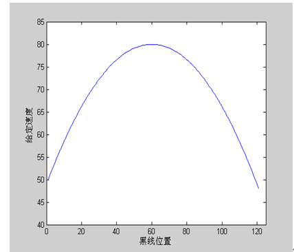
The specific code in the program is as follows: sPID.vi_Ref = g_HighestSpeed – (59 – g_Control) * (59 – g_Control) * (g_HighestSpeed- g_LowestSpeed)/ 3481, where g_HighestSpeed is the maximum speed, g_LowestSpeed is the minimum speed, and g_Control is the black line position, ranging from 0 to 120. In Figure 4.10, g_HighestSpeed is 80, and g_LowestSpeed is 50.
However, this method has certain limitations. On the one hand, the vehicle does not achieve the best control effect when accelerating from turns to straight sections and decelerating from straight sections to turns; the deceleration when entering a turn is not quick enough, and the timing for accelerating from a straight section is not timely enough. Therefore, we made further improvements, dynamically changing the maximum point (the highest speed on straight sections) and minimum point (the lowest speed on turns) in the quadratic curve based on the characteristics of the black line position when entering turns, resulting in better control effects. On the other hand, we did not consider the situation of rapid sprints on long straight sections during actual competitions; pre-setting the straight-line speed in the program was not flexible or reasonable. Therefore, we dynamically increased the straight-line speed g_HighestSpeed in the program based on track conditions, allowing the vehicle to fully exert its potential on long straight sections.
4.6 OpenArtMini Module Control
For the visual recognition part, we used the OpenArt Mini kit from Zhufei Technology, deploying a simple convolutional neural network and quantifying the model through tflite, ultimately deploying it on OpenArt Mini to achieve recognition of animals, fruits, QR codes, and numbers. Additionally, we implemented the activation of the laser by setting the PWM channel duty cycle of the module.
Some code is shown below:
Chapter 5 Debugging Process
5.1 Development Tools
The program was developed under the IAR Embedded Workbench IDE, which is an integrated development environment developed by IAR Systems for ARM microprocessors (hereinafter referred to as IAR EWARM). Compared to other ARM development environments, IAR EWARM is characterized by ease of entry, convenience of use, and compact code.
EWARM includes a full software simulation program (simulator). Users can simulate the software operating environment of various ARM cores, external devices, and even interrupts without any hardware support. This allows understanding and evaluating the functions and usage of IAR EWARM.
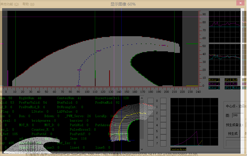
5.2 Upper Computer Image Display
5.2.1 C# Static Upper Computer
To observe the intuitive effects of images captured by the camera, we also used VS2012 C# as an auxiliary development and debugging tool.
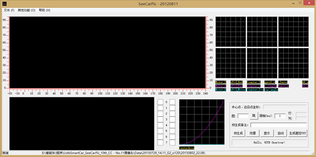
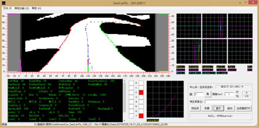
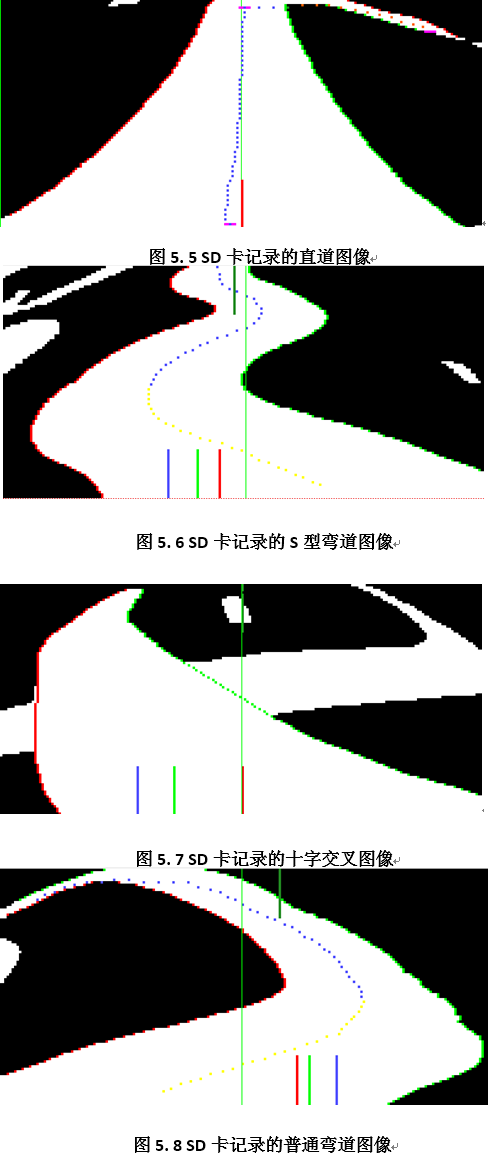
The typical track images recorded during the motion of the model car are shown in Figures 5.5 to 5.9.
5.3 SD Card Module
5.3.1 Introduction to SD Cards
SD cards (Secure Digital Memory Cards) are a new generation of memory devices based on semiconductor flash memory. They were jointly developed by Panasonic, Toshiba, and SanDisk in August 1999, with sizes comparable to a postage stamp and weighing only 2 grams, yet possessing high memory capacity, fast data transfer rates, great mobility, and excellent security. The data storage management of SD cards can be similar to the disk management system of hard drives, using FAT format for data storage.
The SD card interface supports both SD mode and SPI mode, allowing the host system to choose either mode. The SPI mode allows for a simple and general SPI channel interface; however, this mode is slower than the SD mode. Since the Freescale series microcontrollers have SPI interfaces, we used the SPI mode for the SD card.
5.3.2 Introduction to SPI Bus
SPI (Serial Peripheral Interface) bus technology is a synchronous serial bus interface launched by MOTOROLA, and it is one of the most commonly used serial expansion interfaces in microcontroller application systems. The SPI bus mainly transmits data through three wires: the synchronous clock line SCK, the master input/slave output data line MISO, and the master output/slave input data line MOSI, along with a low-level active slave chip select line CS. The chip select signal and synchronous clock pulse of the SPI system are provided by the host. Data on the SPI bus is transmitted in bytes, with each byte being 8 bits, and each command or data block is byte-aligned (an integer multiple of 8 clock cycles). All communication between the host and the SD card is controlled by the host, which must first pull the chip select signal CS (card select) low before sending commands to the SD card. The SD card must respond to any command sent by the host, and different commands have different response formats (1 or 2 bytes of response). In addition to responding to commands, the SD card must also respond to each data block sent by the host during write operations (sending a special data response flag to the host).
5.3.3 Software Implementation
First, the SPI module must be set to master mode, and relevant registers must be configured to differentiate between high speed and low speed. The software design for the SD card mainly includes two parts: the power-on initialization process for the SD card and the read/write operations for the SD card. The flowchart for the SD card initialization program is shown in Figure 5.10.
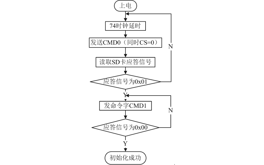
After powering on the SD card, the host must first send 74 clock cycles to complete the power-up process. After powering up, the SD card automatically enters SD bus mode and sends a reset command (CMD0) to the SD card. If the chip select signal CS is low at this time, the SD card enters SPI bus mode; otherwise, it operates in SD bus mode. The SD card will issue a response signal upon entering SPI mode; if the response signal read by the host is 01, it indicates that the SD card has entered SPI mode, at which point the host can continuously send command words (CMD1) to the SD card and read the response signal until the response signal is 00, indicating that the SD card has completed the initialization process and is ready to accept the next command.
After this, the system can read the various registers of the SD card and perform read/write operations, with each read/write operation performed by sector, operating on 512 bytes each time.
Chapter 6 Main Technical Parameters of the Model Car
Basic parameters of the racing car
-
Length: 295mm -
Width: 183mm -
Height: 230mm -
Weight: 1200g -
Power Consumption: No Load: 10W -
With Load: Greater than 12W -
Total Capacitance: 2500uF -
Sensor: 1 CMOS Camera -
Gyroscope: 1 -
Encoder: 2 -
OpenArt Mini: 1 -
Number of Servo Motors: 1 (in addition to the original driving motor and steering servo) -
Track Information Detection: Field of View (Near/Far): 20cm/240cm -
Precision (Near/Far): 2/12.5mm -
Frequency: 50Hz
Conclusion
Since registering for the 16th National College Student Intelligent Car Competition, our team members have progressively worked through searching for information, designing structures, assembling the model car, and writing programs, ultimately achieving our initial goals and establishing the current design scheme.
This technical report primarily introduces the basic ideas during competition preparations, including innovations in mechanical, circuit, and most importantly, control algorithms. In terms of mechanical structure, we analyzed the overall mass distribution of the vehicle, adjusted the center of gravity position, and optimized the mechanical structure. Regarding the circuit, we categorized the modules and designed them separately for the minimum system, mainboard, motor drive, etc., preparing several sets of schemes based on the literature review; then we conducted experiments and ultimately determined our final circuit diagram in the manner mentioned in this report. In terms of programming, we used C language for programming, debugging the program using the recommended development tools for the competition. After continuous discussions and improvements among team members, we finally designed a relatively universal and stable program. In this algorithm, we adjusted the vehicle speed based on road conditions, achieving acceleration on straight sections and deceleration on turns, ensuring that the vehicle completes the entire course in the shortest time.
During the past few months of preparation, we have received strong support from the school and college in terms of venue and funding. We would like to extend our special thanks to the leaders of the school and college who have continuously supported and paid attention to the intelligent car competition, as well as to all instructors and guiding seniors. We also thank the competition organizing committee for organizing such a meaningful competition.
Now, facing the upcoming competition, after nearly five months of thorough preparation and the test of the North China competition, we are confident in achieving excellent results in the national competition. Although our knowledge may still be lacking and our considerations may not be comprehensive, this technical report, as a crystallization of our team’s hard work, embodies the efforts and wisdom of each member of our team. With its birth, this experience will accompany us for a lifetime, becoming our most cherished memory.