Chapter 16
SysTick – System Timer
References for this Chapter
“DEFINITIVE GUIDE TO ARM CORTEX-M23 AND CORTEX-M33 PROCESSORS” – Section 11.2 SysTick Timer, “Cortex-M3 Kernel Programming Manual” – Section 4.5 SysTick Timer (STK), and Section 4.48 SHPRx, which provides an introduction to SysTick and detailed descriptions of its registers. Since SysTick is a peripheral of the CORTEX-M33 core, the definitions of the registers and some library functions are implemented in the header file core_cm33.h. Therefore, when learning about SysTick, you can refer to these two resources: one is the documentation, and the other is the source code.
16.1
Introduction to SysTick System Timer
The SysTick – System Timer is a peripheral within the CM33 core, embedded in the NVIC. The system timer is a 24-bit down-counting timer, where each count corresponds to a time of 1/SYSCLK, typically with SYSCLK set to 200MHz. When the value in the reload value register decrements to 0, the system timer generates an interrupt, and this process repeats.
Since SysTick is a peripheral of the CM33 core, all microcontrollers based on the CM33 core have this system timer, making it easy to port software to CM33 microcontrollers. The system timer is generally used in operating systems to generate time bases and maintain the heartbeat of the operating system.
16.2
Introduction to SysTick Registers
The SysTick – System Timer has four registers, briefly described as follows. When using SysTick for timing, only the first three registers need to be configured; the last calibration register is not required.
Table 1: Summary of SysTick Registers
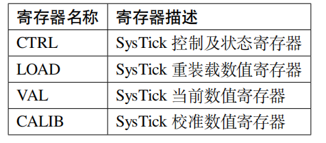
Table 2: SysTick Control and Status Register
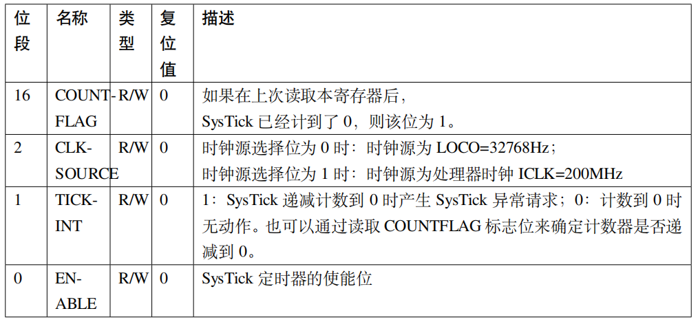
Table 3: SysTick Reload Value Register

Table 4: SysTick Current Value Register
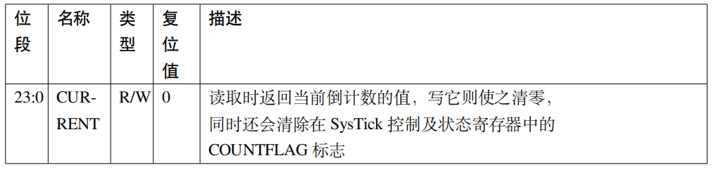
Table 5: SysTick Calibration Value Register
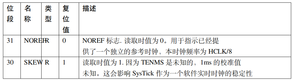
The calibration value register of the system timer is not needed in timing experiments. This chapter will not explain this register in detail; interested readers can research it themselves.
16.3
Using SysTick for Timing Experiments
Using SysTick to generate a 1s time base, the LED blinks at a frequency of 1s.
16.3.1
Hardware Design
SysTick is an internal peripheral of the microcontroller, requiring no additional hardware circuits; only an LED is needed.
16.3.2
Software Design
This section will explain only the core part of the code; some variable settings and header file inclusions are not covered. For the complete code, please refer to the accompanying project for this chapter. We created two files: bsp_SysTick.c and bsp_SysTick.h to store the SysTick driver program, interrupt service functions, and related macro definitions.
16.3.2.1
Programming Key Points
-
Set the value of the reload register
-
Clear the value of the current value register
-
Configure the control and status register
16.3.2.2
Code Analysis
SysTick is a peripheral of the core, and the relevant register definitions and library functions are in the core-related library file core_cm33.h.
16.3.2.2.1 SysTick Configuration Library Function
Listing 1: Code Listing 17-1 SysTick Configuration Library Function
Swipe left and right to view the full content
__STATIC_INLINE uint32_t SysTick_Config(uint32_t ticks) { // Impossible reload value, out of range if ((ticks - 1UL) > SysTick_LOAD_RELOAD_Msk) { return (1UL); } // Set reload register SysTick->LOAD = (uint32_t)(ticks - 1UL); // Set interrupt priority NVIC_SetPriority(SysTick_IRQn, (1UL << __NVIC_PRIO_BITS) - 1UL); // Set current value register SysTick->VAL = 0UL; // Set the clock source for the system timer to ICLK=200M // Enable system timer interrupt // Enable timer SysTick->CTRL = SysTick_CTRL_CLKSOURCE_Msk | SysTick_CTRL_TICKINT_Msk | SysTick_CTRL_ENABLE_Msk; return (0UL); }When programming with the firmware library, we only need to call the library function SysTick_Config(). The parameter ticks is used to set the value of the reload register, which must not exceed the maximum reload register value of 224. When the value of the reload register decrements to 0, an interrupt is generated, and the reload register value is loaded again and decrements in count, repeating this process. Next, set the interrupt priority, and finally configure the system timer clock to ICLK=200M, enabling the timer and timer interrupt, thus completing the configuration of the system timer with a single library function.
The SysTick_Config() library function mainly configures three registers in SysTick: LOAD, VAL, and CTRL; for specific details, please refer to the code comments.
16.3.2.2.2 Configuring SysTick Interrupt Priority
The SysTick_Config() library function mainly configures three registers in SysTick: LOAD, VAL, and CTRL; for specific details, please refer to the code comments. It also calls the library function NVIC_SetPriority() to configure the interrupt priority of the system timer, which is also defined in core_cm33.h, with the prototype as follows:
Listing 2: Code Listing 17-2 NVIC Interrupt Priority Configuration Function
Swipe left and right to view the full content
__STATIC_INLINE void __NVIC_SetPriority(IRQn_Type IRQn, uint32_t priority) { if ((int32_t)(IRQn) >= 0) { NVIC->IPR[((uint32_t)IRQn)] = (uint8_t)((priority << (8U - __NVIC_PRIO_BITS)) & (uint32_t)0xFFUL); } else { SCB->SHPR[(((uint32_t)IRQn) & 0xFUL) - 4UL] = (uint8_t)((priority << (8U - __NVIC_PRIO_BITS)) & (uint32_t)0xFFUL); }}

Need Technical Support?
If you have any questions while using Renesas MCU/MPU products, you can scan the QR code below or copy the URL into your browser to access the Renesas Technical Forum for answers or to obtain online technical support.

https://community-ja.renesas.com/zh/forums-groups/mcu-mpu/
To be continued
Recommended Reading

Software Design – Practical Guide to Renesas RA Series FSP Library Development (38)

Introduction to Interrupt Processes – Practical Guide to Renesas RA Series FSP Library Development (39)