
Click the blue text
Follow us
1. Overview
Ethernet refers to the baseband local area network specification created by Xerox and jointly developed by Xerox, Intel, and DEC. Ethernet uses CSMA/CD (Carrier Sense Multiple Access with Collision Detection) technology and operates at a rate of 10M/S over various types of cables. Ethernet is similar to the IEEE 802.3 series standards. It is not a specific network but a technical specification. Ethernet is the most widely used communication protocol standard in existing local area networks today. This standard defines the types of cables and signal processing methods used in local area networks (LANs). Ethernet transmits information packets between interconnected devices at rates of 10 to 100 Mbps, with twisted pair cable 10 Base T Ethernet being the most widely used Ethernet technology due to its low cost, high reliability, and 10 Mbps speed.
Ethernet is widely used in various computer local area network technologies and is commonly applied in the following scenarios:
Industrial Automation: Ethernet has extensive applications in the field of industrial automation. It can meet the demands of industrial automation systems for large data transmission and real-time performance, support multiple device connections, adapt to harsh environments such as high temperatures and humidity, and is suitable for complex industrial environments.
Enterprise Networks: In enterprise networks, Ethernet is used to build high-speed, stable internal networks that support the transmission of multiple services such as data, video, and voice. It is widely used in large enterprises and data centers, providing high-speed data transmission support.
Intelligent Transportation: In intelligent transportation systems, Ethernet connects traffic monitoring devices to achieve real-time transmission of traffic data. This helps improve the efficiency and safety of traffic management.
Remote Monitoring: In remote monitoring systems, Ethernet is used to transmit monitoring data to control centers, enhancing monitoring efficiency. It is widely used in various remote monitoring scenarios, such as environmental monitoring and equipment monitoring.
Data Centers: Data centers use Ethernet to connect servers and storage devices, enabling high-speed data exchange. 10 Gigabit Ethernet is particularly widely used in data centers to meet the demands of high-performance computing and big data processing.
Supercomputing Centers: In supercomputing centers, 10 Gigabit Ethernet devices provide high-density ports and fast switching performance, meeting the needs of high-performance computer architectures and networks, promoting the development of computer science research.
2. Basic Structure of Microcontroller Ethernet System
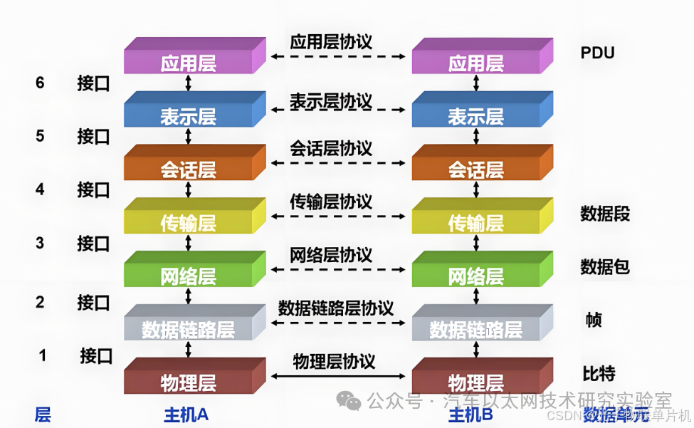
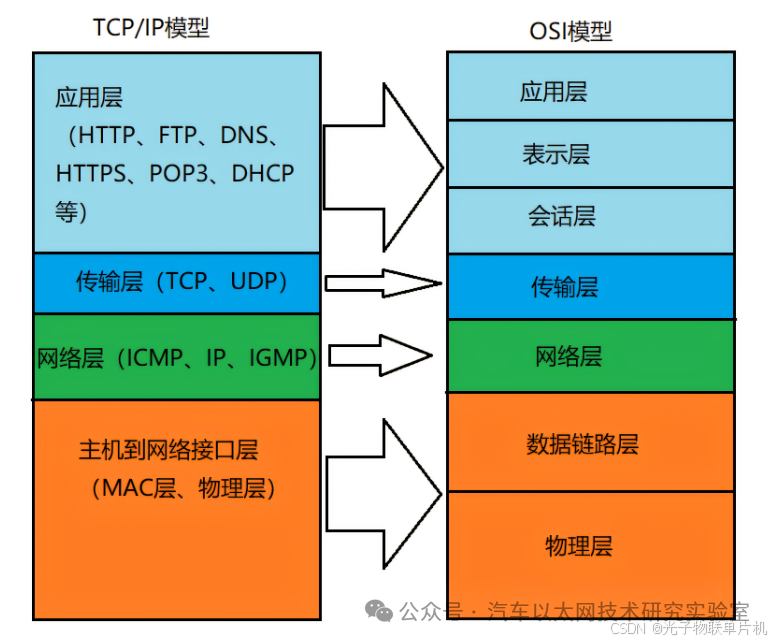
1. OSI Seven-Layer Model
The OSI Seven-Layer Model is a network communication framework defined by the International Organization for Standardization (ISO), aimed at providing a standardized method for communication between different computer systems. This model divides the network communication process into seven layers, from the physical layer to the application layer, with each layer having its specific functions and protocols.
2. Components Required for Microcontroller Ethernet Functionality
The typical components required for a microcontroller to form an Ethernet connection are: microcontroller + MAC + PHY + RJ45.
The STM32F407VET6 has an internal MAC, so the main components needed to form an Ethernet connection are
STM32F407VET6 + PHY + RJ45.
The commonly used Ethernet PHY chips are DP83848 and LAN8720.
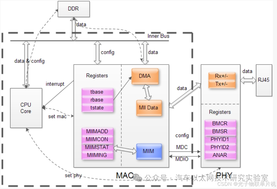
Ethernet MAC: The Media Access Control sublayer protocol is located in the lower half of the data link layer of the OSI seven-layer protocol and is mainly responsible for controlling and connecting to the physical medium of the physical layer. The main functions of the MAC protocol include determining whether data can be sent when transmitting data; if it can be sent, it adds some control information to the data and ultimately sends the data and control information in a specified format to the physical layer; when receiving data, the MAC protocol first checks whether the input information has transmission errors; if there are no errors, it removes the control information and sends it to the logical link control layer.
Ethernet PHY: The physical layer interface transceiver is an important component in network communication, implementing the physical layer of the OSI model. The IEEE-802.3 standard defines Ethernet PHY, including multiple sublayers such as MII/GMII (Media Independent Interface), PCS (Physical Coding Sublayer), PMA (Physical Medium Attachment Sublayer), PMD (Physical Medium Dependent Sublayer), and MDI sublayer. These sublayers collectively define the electrical and optical signals, line status, clock reference, data encoding, and circuits required for data transmission and reception, providing a standard interface to data link layer devices.
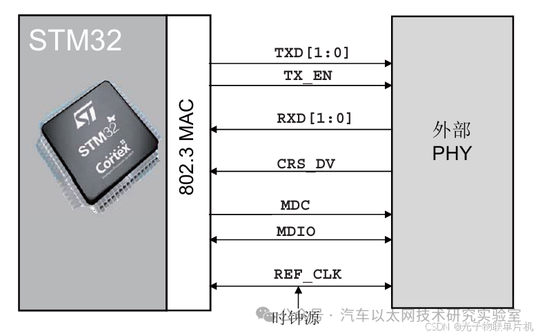
3. Internal Structure of STM32F407VET6 Microcontroller Ethernet
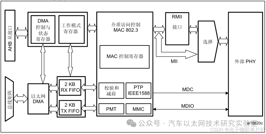
When sending data over Ethernet, the microcontroller first sends the data from the system memory to the transmit FIFO (Tx FIFO) for buffering via DMA, and then sends it through the MAC core, which communicates with the external PHY via RMII or MII interface.
When receiving data over Ethernet, the receive FIFO (Rx FIFO) stores the Ethernet frames received through the line until these frames are transferred to the system memory via DMA.
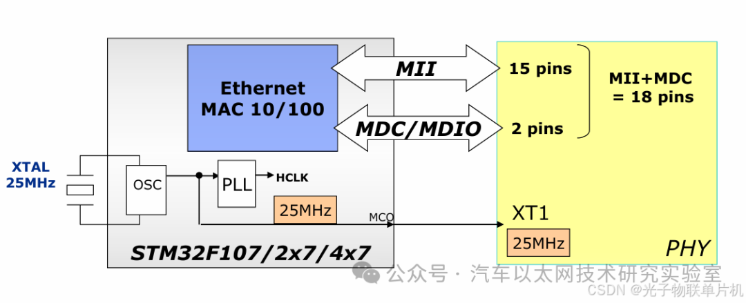
1. Introduction to MII Interface
The Media Independent Interface (MII) defines the interconnection between the MAC sublayer and PHY at data transmission rates of 10 Mbit/s and 100 Mbit/s.
MII Connection Diagram
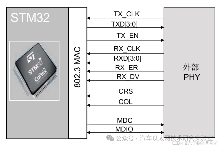
2. Introduction to RMII Interface
The Reduced Media Independent Interface (RMII) specification reduces the number of pins between the microcontroller Ethernet peripheral and the external PHY at 10/100 Mbit/s.
RMII Connection Diagram
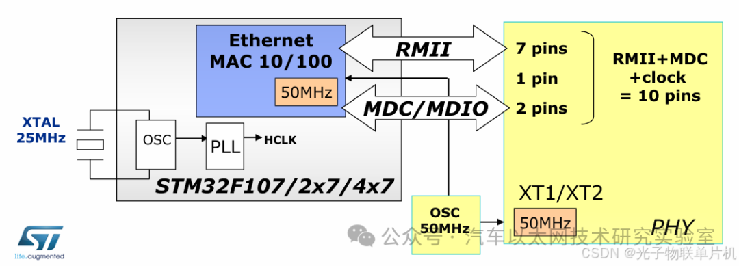
Comparing the two connection methods above, RMII provides a solution that simplifies hardware design while maintaining or increasing data transmission rates by reducing the number of signal lines and increasing clock frequency. This interface is particularly useful in applications where cost, performance, and complexity need to be balanced, making RMII the most common connection method in STM32 development.
4. Introduction to LWIP TCP/IP Protocol Stack
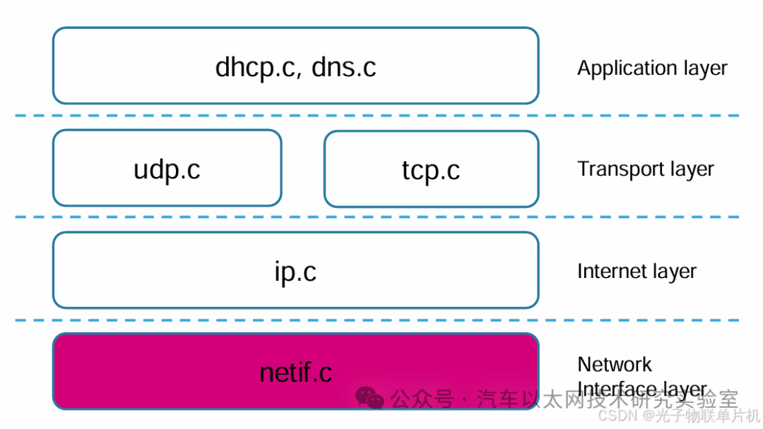
The TCP/IP protocol stack is a collection of network protocols that allows different electronic devices to communicate over the Internet. This protocol adopts a four-layer structure, consisting of the application layer, transport layer, network layer, and network interface layer, with each layer depending on the layer below it while providing services to the layer above it.
The TCP/IP protocol stack does not completely correspond to the traditional OSI model. The TCP/IP protocol is a simplified model that emphasizes the actual protocol implementation and the practical operation of the Internet.
Lightweight IP (LWIP) is a lightweight TCP/IP protocol developed by Adam Dunkels at the Swedish Institute of Computer Science (SICS). The design goal of LwIP is to implement a relatively complete TCP/IP protocol stack with minimal resource consumption (RAM), while reducing RAM usage while maintaining the main functions of the TCP protocol.
LwIP can be ported to run on an operating system or can run independently without an operating system. It requires only a few KB of RAM and about 40K of ROM to operate, making the LwIP protocol stack suitable for use in low-end embedded systems.
LwIP conforms to the TCP/IP model architecture, specifying the format, transmission, routing, and reception of data to achieve end-to-end communication.
Application Layer: lwIP provides the implementation of the TCP/IP protocol stack, including protocols such as HTTP, MQTT, etc.
Transport Layer: lwIP implements TCP and UDP protocols.
Network Layer: lwIP implements the IP protocol.
Network Interface Layer: lwIP does not implement this layer; it is implemented by hardware.
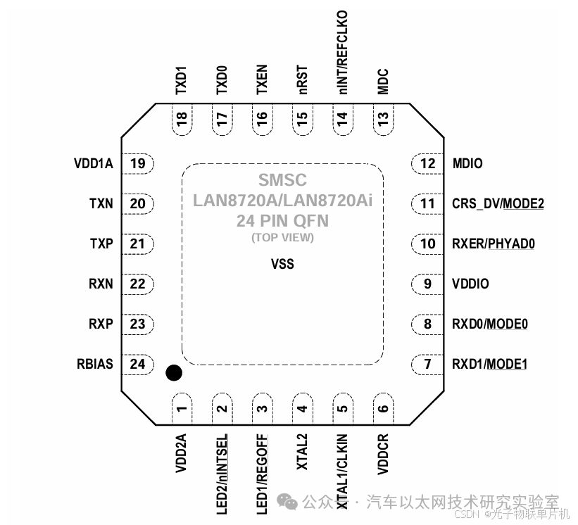
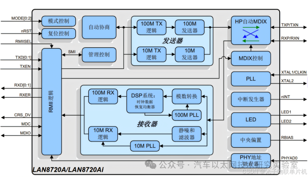
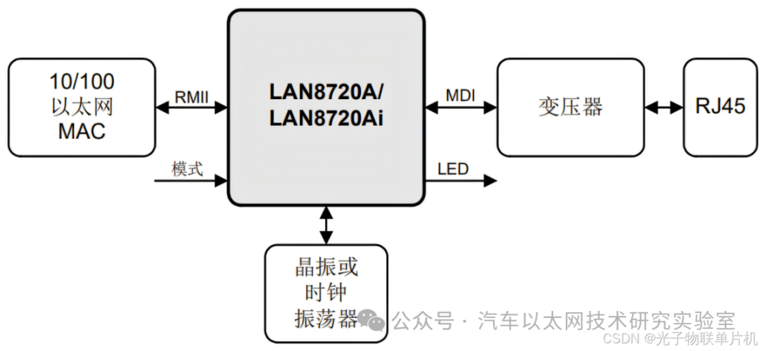
5. Introduction to PHY Transceiver LAN8720
LAN8720A is a low-power 10/100M Ethernet PHY chip that complies with the EEE802.3-2005 standard and supports communication with the Ethernet MAC layer via RMII interface. It has a built-in 10-BASE-T/100BASE-TX full-duplex transmission module, supporting transmission speeds of 10Mbps and 100Mbps. LAN8720A features auto-negotiation, allowing it to automatically select the best connection method (speed and duplex mode) with the destination host, and supports HP Auto-MDIX automatic crossover functionality, enabling direct or crossover connections without changing cables. Additionally, it supports configuration and management via SMI serial management interface and MAC interface.
1. Internal Block Diagram of LAN8720
2. LAN8720 Application Circuit
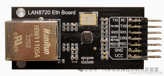
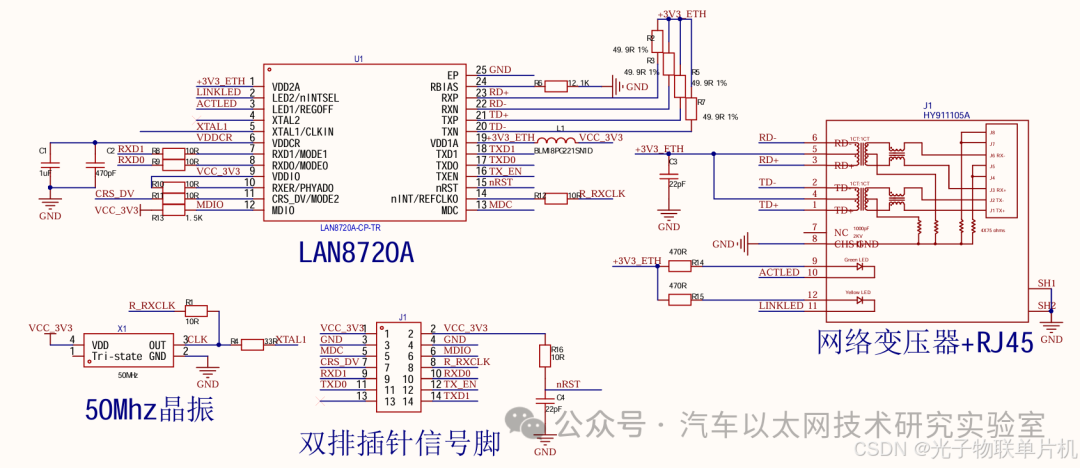
3. LAN8720 Ethernet Module
The LAN8720 Ethernet module integrates the PHY and RJ45 on a small board, allowing the development board to connect to the module via RMII to form an Ethernet system.
Module Reference Schematic
6. Configuring a LWIP TCP/IP Communication Protocol Experiment with CubeMX
Hardware Preparation:
Connect STLINK to the STM32F407VET6 development board and connect STLINK to the computer USB port. Connect the LAN8720 module to the development board, and connect the network cable to the RJ45 port of the module and the computer.
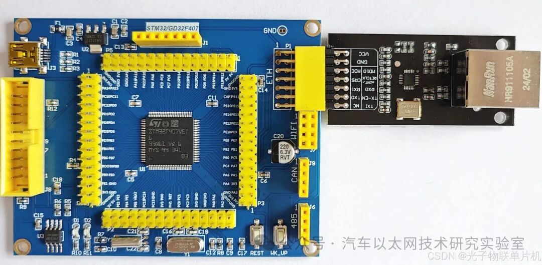
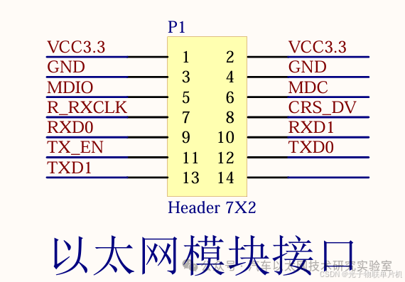
Development Board Ethernet Interface Definition:
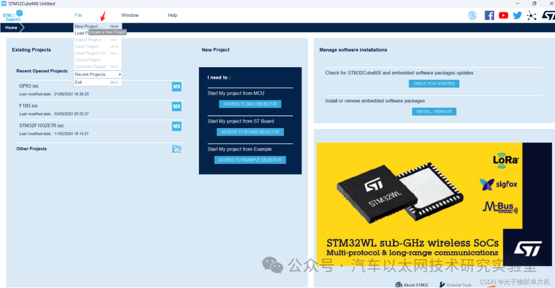
Open STM32CubeMX software and create a new project
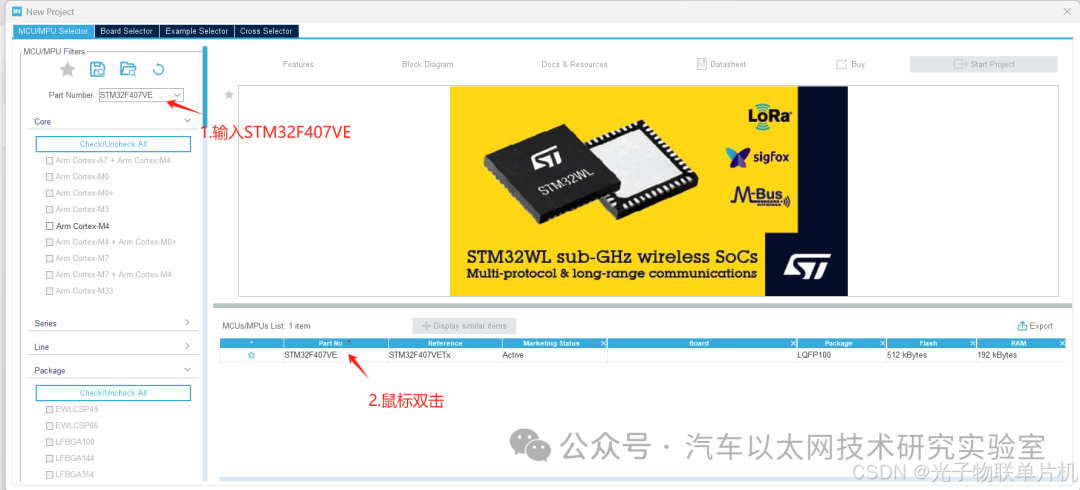
Enter STM32F407VE in the Part Number field, then double-click to create a new project
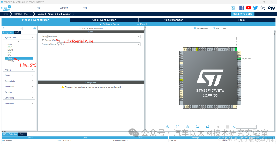
Configure the download port pins
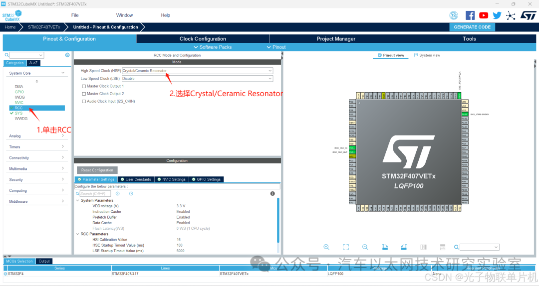
Configure the external crystal oscillator pins
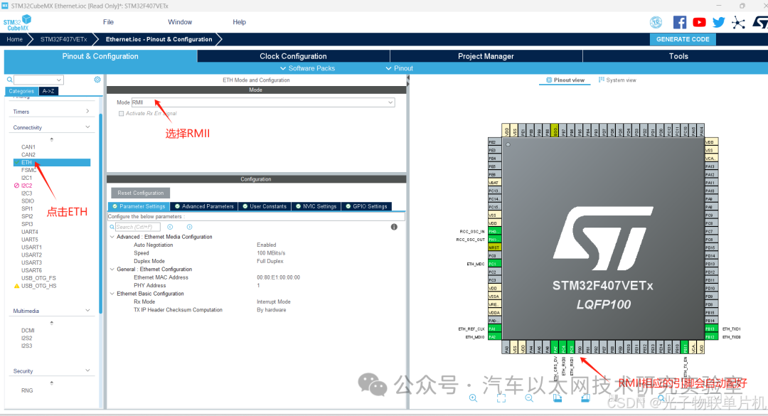
Configure the Ethernet RMII interface
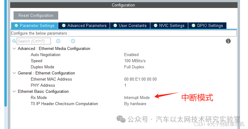
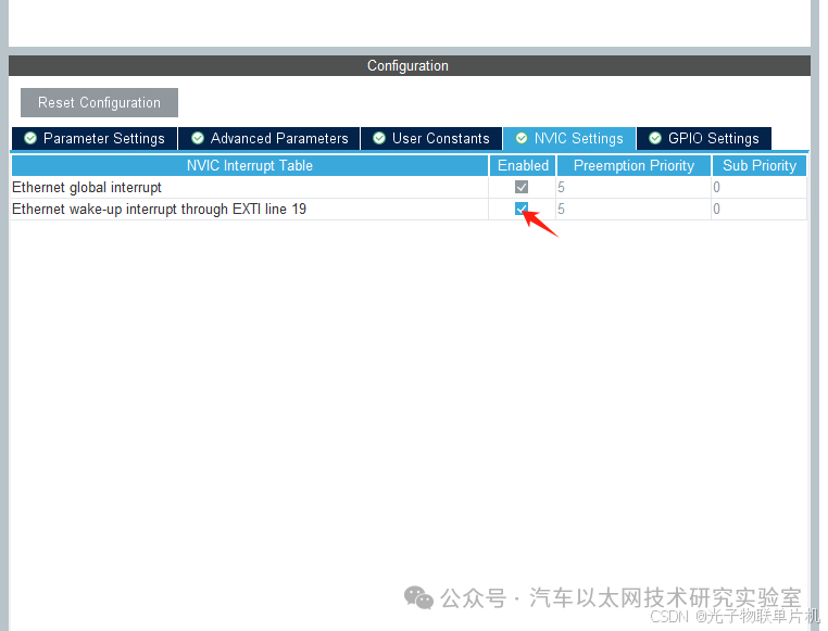
Configure interrupts
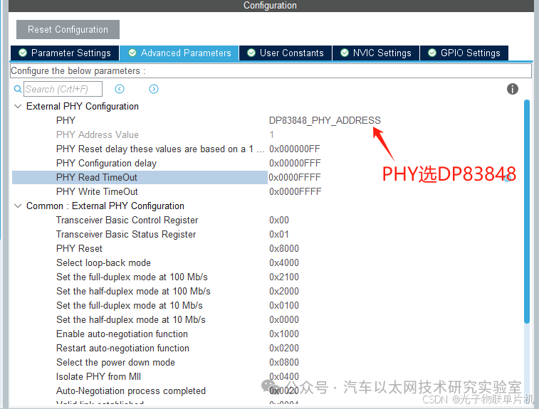
Select PHY DP83848
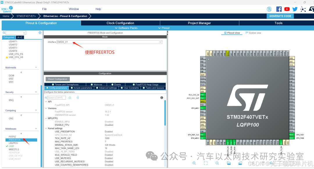
Enable FreeRTOS
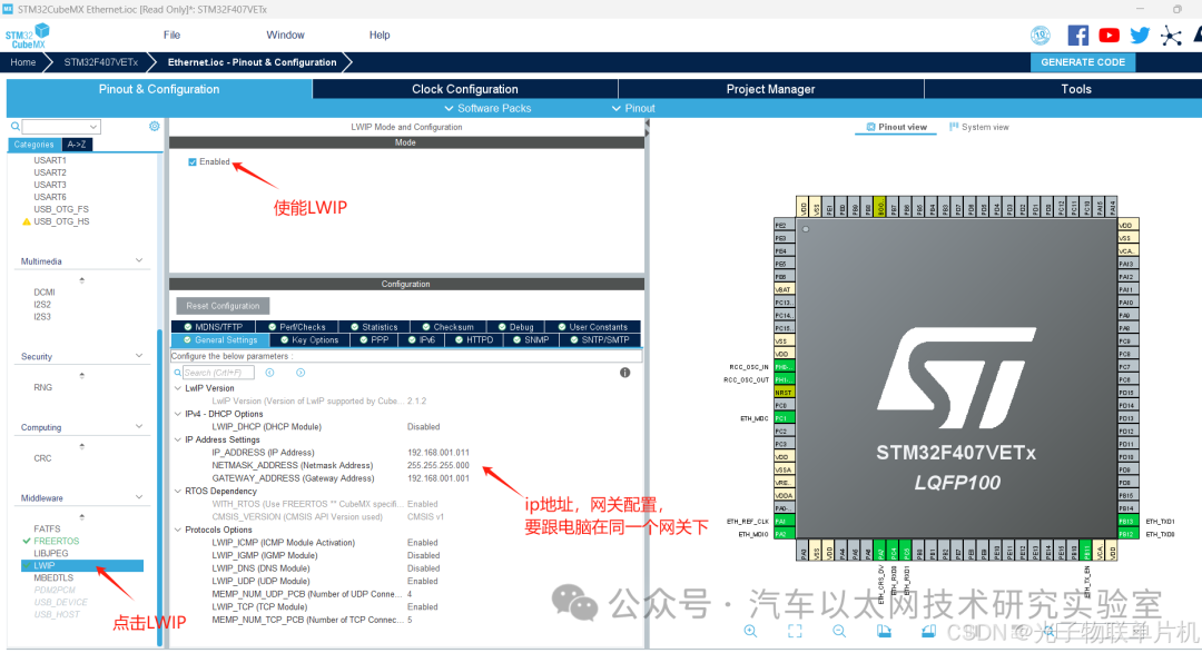
LWIP configuration, IP address, mask, gateway configuration
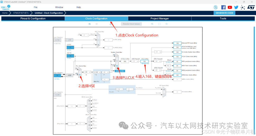
Configure system clock frequency to 168MHz, using external crystal oscillator
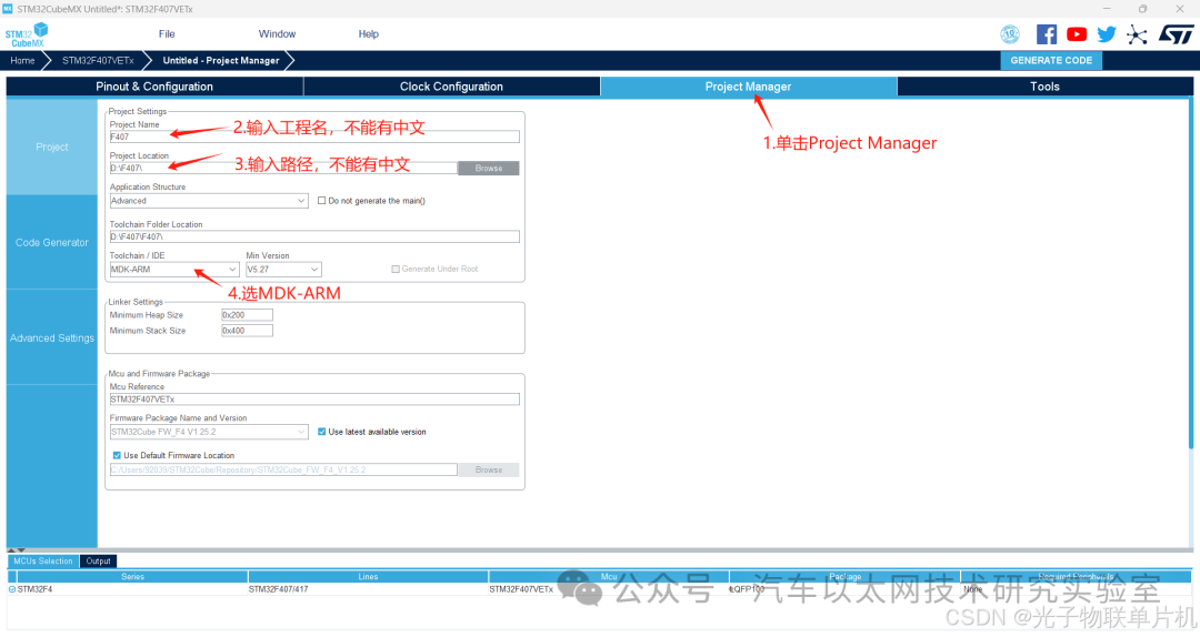
Configure project file name, save path, KEIL5 project output method
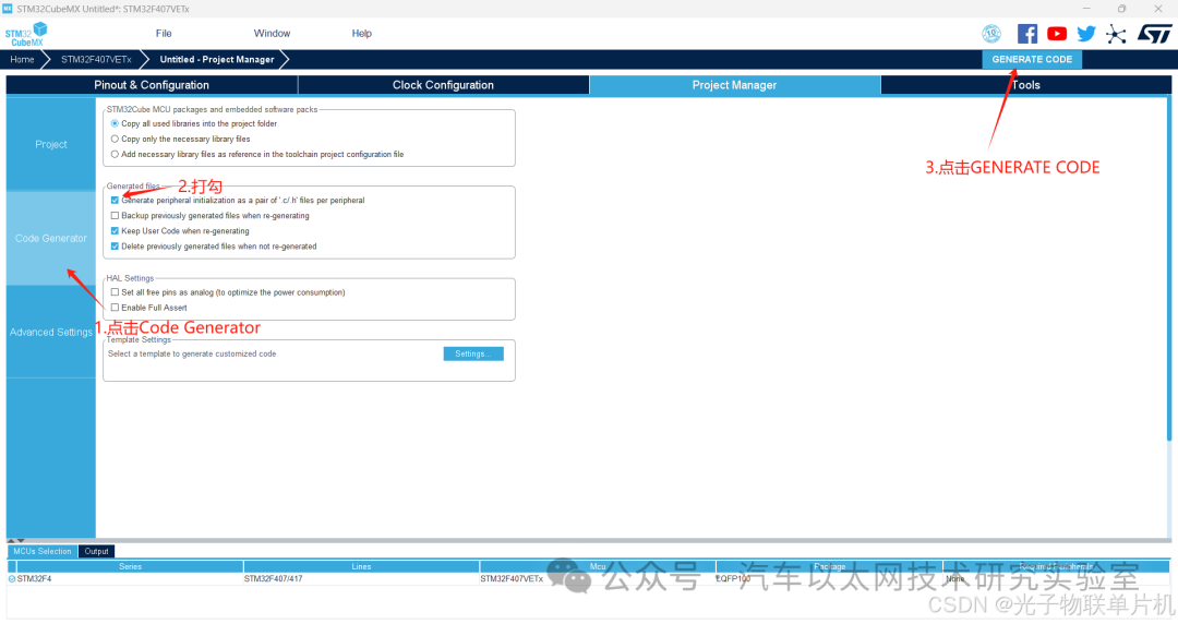
Generate project
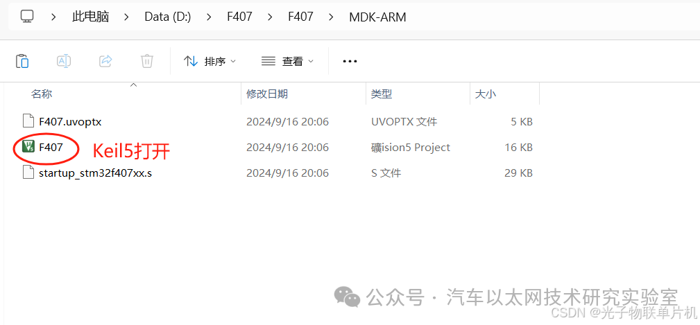
Open the project with Keil5
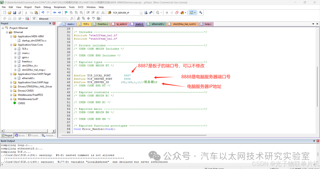
Add code
Check if the server IP address configuration is correct
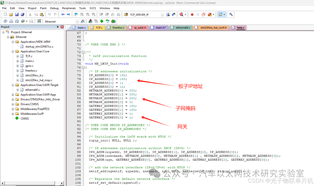
Check if the board’s IP address and gateway are correct
The main code is as follows:
-
#define TCP_LOCAL_PORT 8887
-
#define TCP_SERVER_PORT 8888
-
#define TCP_SERVER_IP 192,168,1,11 // Server IP
-
void MX_LWIP_Init(void)
-
{
-
/* IP addresses initialization */
-
IP_ADDRESS[0] = 192;
-
IP_ADDRESS[1] = 168;
-
IP_ADDRESS[2] = 1;
-
IP_ADDRESS[3] = 12; // Board IP address
-
NETMASK_ADDRESS[0] = 255; // Mask
-
NETMASK_ADDRESS[1] = 255;
-
NETMASK_ADDRESS[2] = 255;
-
NETMASK_ADDRESS[3] = 0;
-
GATEWAY_ADDRESS[0] = 192;
-
GATEWAY_ADDRESS[1] = 168;
-
GATEWAY_ADDRESS[2] = 1;
-
GATEWAY_ADDRESS[3] = 1; // Gateway
-
/* USER CODE BEGIN IP_ADDRESSES */
-
/* USER CODE END IP_ADDRESSES */
-
/* Initialize the LwIP stack with RTOS */
-
tcpip_init(NULL, NULL);
-
/* IP addresses initialization without DHCP (IPv4) */
-
IP4_ADDR(&ipaddr, IP_ADDRESS[0], IP_ADDRESS[1], IP_ADDRESS[2], IP_ADDRESS[3]);
-
IP4_ADDR(&netmask, NETMASK_ADDRESS[0], NETMASK_ADDRESS[1], NETMASK_ADDRESS[2], NETMASK_ADDRESS[3]);
-
IP4_ADDR(&gw, GATEWAY_ADDRESS[0], GATEWAY_ADDRESS[1], GATEWAY_ADDRESS[2], GATEWAY_ADDRESS[3]);
-
/* Add the network interface (IPv4/IPv6) with RTOS */
-
netif_add(&gnetif, &ipaddr, &netmask, &gw, NULL, ðernetif_init, &tcpip_input);
-
/* Registers the default network interface */
-
netif_set_default(&gnetif);
-
if (netif_is_link_up(&gnetif))
-
{
-
/* When the netif is fully configured this function must be called */
-
netif_set_up(&gnetif);
-
}
-
else
-
{
-
/* When the netif link is down this function must be called */
-
netif_set_down(&gnetif);
-
}
-
/* Set the link callback function, this function is called on change of link status*/
-
netif_set_link_callback(&gnetif, ethernetif_update_config);
-
/* Create a binary semaphore used for informing ethernetif of frame reception */
-
osSemaphoreDef(Netif_SEM);
-
Netif_LinkSemaphore = osSemaphoreCreate(osSemaphore(Netif_SEM), 1);
-
link_arg.netif = &gnetif;
-
link_arg.semaphore = Netif_LinkSemaphore;
-
/* Create the Ethernet link handler thread */
-
/* USER CODE BEGIN OS_THREAD_DEF_CREATE_CMSIS_RTOS_V1 */
-
osThreadDef(LinkThr, ethernetif_set_link, osPriorityBelowNormal, 0, configMINIMAL_STACK_SIZE * 2);
-
osThreadCreate(osThread(LinkThr), &link_arg);
-
/* USER CODE END OS_THREAD_DEF_CREATE_CMSIS_RTOS_V1 */
-
/* USER CODE BEGIN 3 */
-
/* USER CODE END 3 */
-
}
-
/***********************************************************************/
-
Function Name: void TCP_Client_Send_Data(unsigned char *buff)
-
Function: TCP client send data function
-
Input Parameters:
-
Output Parameters:
-
Written on: 2013.4.25
-
Author:
-
Note: for(cpcb = tcp_active_pcbs; cpcb != NULL; cpcb = cpcb->next)
-
***********************************************************************/
-
err_t TCP_Client_Send_Data(struct tcp_pcb *cpcb, unsigned char *buff, unsigned int length)
-
{
-
err_t err;
-
err = tcp_write(cpcb, buff, length, TCP_WRITE_FLAG_COPY); // Send data
-
tcp_output(cpcb);
-
//tcp_close(tcp_client_pcb); // Close connection after sending data, choose based on specific situation
-
return err;
-
}
-
extern union tcp_listen_pcbs_t tcp_listen_pcbs;
-
extern struct tcp_pcb *tcp_active_pcbs; /* List of all TCP PCBs that are in a
-
/***********************************************************************/
-
Function Name: Check_TCP_Connect(void)
-
Function: Check connection
-
Input Parameters:
-
Output Parameters:
-
Written on: 2013.4.25
-
Author:
-
Note: for(cpcb = tcp_active_pcbs; cpcb != NULL; cpcb = cpcb->next)
-
***********************************************************************/
-
struct tcp_pcb *Check_TCP_Connect(void)
-
{
-
struct tcp_pcb *cpcb = 0;
-
connect_flag = 0;
-
for(cpcb = tcp_active_pcbs; cpcb != NULL; cpcb = cpcb->next)
-
{
-
// if(cpcb->local_port == TCP_LOCAL_PORT && cpcb->remote_port == TCP_SERVER_PORT) // If the connection specified by TCP_LOCAL_PORT is not disconnected
-
if(cpcb -> state == ESTABLISHED) // If a response is received, it proves that the connection has been established
-
{
-
connect_flag = 1; // Connection flag
-
break; // Exit the loop
-
}
-
}
-
if(connect_flag == 0) // The port specified by TCP_LOCAL_PORT is not connected or has been disconnected
-
{
-
TCP_Client_Init(TCP_LOCAL_PORT, TCP_SERVER_PORT, TCP_SERVER_IP); // Reconnect
-
cpcb = 0;
-
}
-
return cpcb;
-
}
-
/***********************************************************************/
-
Function Name: err_t RS232_TCP_Connected(void *arg, struct tcp_pcb *pcb, err_t err)
-
Function: Complete RS232 to TCP data sending
-
Input Parameters:
-
Output Parameters:
-
Written on: 2013.4.25
-
Author:
-
Note: This is a callback function that is called when a TCP client requests to establish a connection
-
***********************************************************************/
-
err_t TCP_Connected(void *arg, struct tcp_pcb *pcb, err_t err)
-
{
-
//tcp_client_pcb = pcb;
-
return ERR_OK;
-
}
-
/***********************************************************************/
-
Function Name: TCP_Client_Recv(void *arg, struct tcp_pcb *pcb, struct pbuf *p, err_t err)
-
Function: TCP client receive data callback function
-
Input Parameters:
-
Output Parameters:
-
Written on: 2013.4.25
-
Author:
-
Note: This is a callback function that is called when the TCP server sends data
-
***********************************************************************/
-
err_t TCP_Client_Recv(void *arg, struct tcp_pcb *pcb, struct pbuf *p, err_t err)
-
{
-
struct pbuf *p_temp = p;
-
if(p_temp != NULL)
-
{
-
tcp_recved(pcb, p_temp->tot_len); // Get data length tot_len: length of TCP data block
-
while(p_temp != NULL)
-
{
-
/****** Return data as is *******************/
-
tcp_write(pcb, p_temp->payload, p_temp->len, TCP_WRITE_FLAG_COPY); // payload is the starting position of the TCP data block
-
tcp_output(pcb);
-
p_temp = p_temp->next;
-
}
-
}
-
else
-
{
-
tcp_close(pcb); /* As a TCP server, should not actively close this connection? */
-
}
-
/* Release this TCP segment */
-
pbuf_free(p);
-
err = ERR_OK;
-
return err;
-
}
-
/***********************************************************************/
-
Function Name: TCP_Client_Init(u16_t local_port, u16_t remote_port, unsigned char a, unsigned char b, unsigned char c, unsigned char d)
-
Function: TCP client initialization
-
Input Parameters: local_port local port number; remote_port: target port number; a,b,c,d: server IP
-
Output Parameters:
-
Written on: 2013.4.25
-
Author:
-
Note:
-
***********************************************************************/
-
void TCP_Client_Init(u16_t local_port, u16_t remote_port, unsigned char a, unsigned char b, unsigned char c, unsigned char d)
-
{
-
ip4_addr_t ipaddr, LocalAddress;
-
err_t err;
-
IP4_ADDR(&ipaddr, a, b, c, d); // Server IP address
-
tcp_client_pcb = tcp_new(); /* Create a TCP control block for communication (Clipcb) */
-
if (!tcp_client_pcb)
-
{
-
return ;
-
}
-
//IP4_ADDR(&LocalAddress,192,168,10,11); // Server IP address
-
err = tcp_bind(tcp_client_pcb, IP_ADDR_ANY, local_port); /* Bind local IP address and port number, local IP address has been initialized in LwIP_Init() */
-
if(err != ERR_OK)
-
{
-
return ;
-
}
-
tcp_connect(tcp_client_pcb, &ipaddr, remote_port, TCP_Connected); // Register callback function
-
tcp_recv(tcp_client_pcb, TCP_Client_Recv); /* Set TCP receive callback function */
-
}
-
unsigned char tcp_data[] = “tcp client experiment!\n”;
-
struct tcp_pcb *pcb;
-
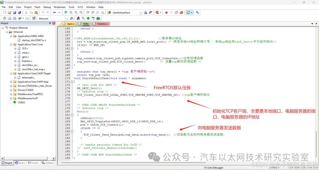
void StartDefaultTask(void const * argument)
-
{
-
/* init code for LWIP */
-
MX_LWIP_Init();
-
/* Infinite loop */
-
TCP_Client_Init(TCP_LOCAL_PORT, TCP_SERVER_PORT, TCP_SERVER_IP); // TCP client initialization
-
/* USER CODE BEGIN StartDefaultTask */
-
/* Infinite loop */
-
for(;;)
-
{
-
osDelay(1000);
-
HAL_GPIO_TogglePin(GPIOC, GPIO_PIN_13 | GPIO_PIN_14);
-
pcb = Check_TCP_Connect();
-
if(pcb != 0)
-
{
-
TCP_Client_Send_Data(pcb, tcp_data, sizeof(tcp_data)); // This function actively sends data to the server
-
}
-
/* Handle periodic timers for LwIP */
-
// LwIP_Periodic_Handle(LocalTime);
-
}
-
/* USER CODE END StartDefaultTask */
-
}
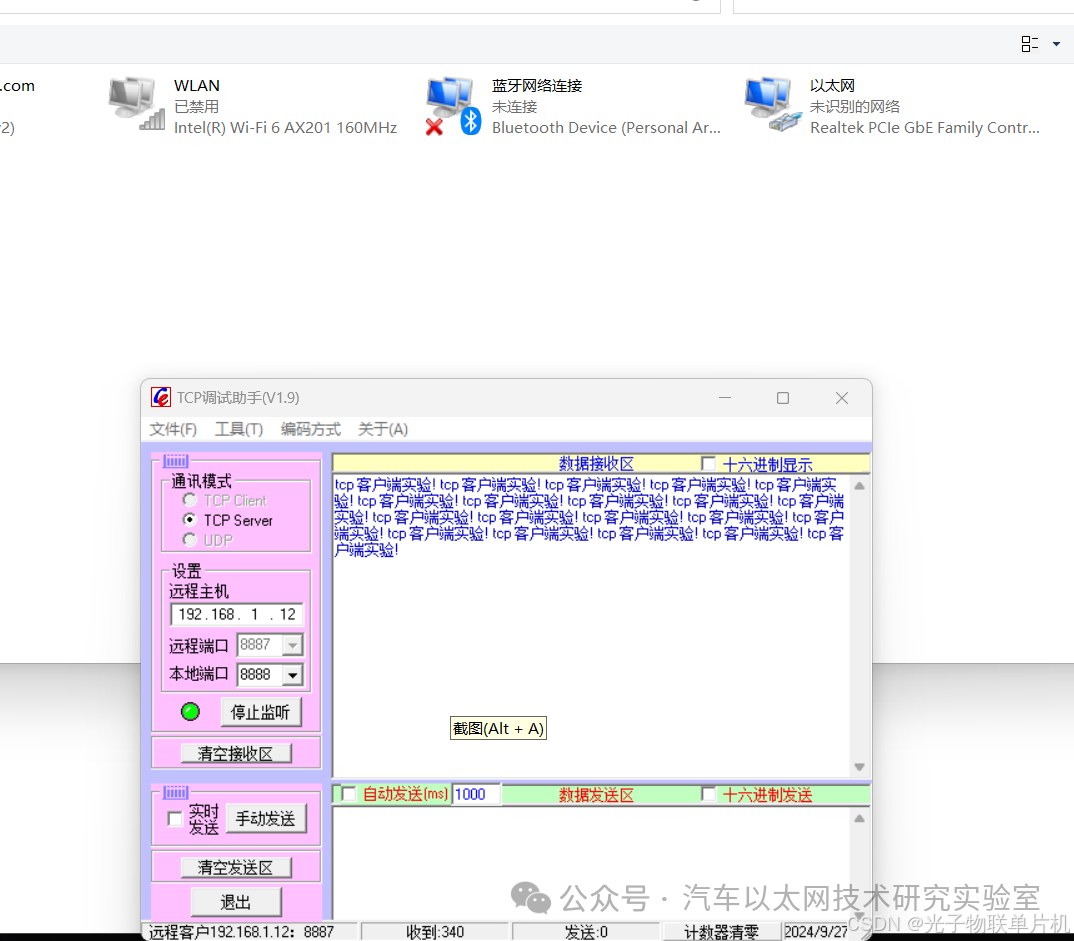
Experiment Effect:
Disable wireless, start Ethernet, open TCP debugging assistant, configure it to server listening mode, listen on port 8888. Shortly after powering on the board, the TCP debugging assistant can see the board with IP address 192.168.1.12 connecting and sending data.
7. Conclusion
The STM32F407 development board combined with the LAN8720 module can connect to the network, enabling remote control, data transmission, and other functions.


*Disclaimer: This article is original or forwarded by the author. If it inadvertently infringes on someone’s intellectual property rights, please inform us and we will delete it immediately. The above images and text are sourced from the internet, and if there is any infringement, please contact us in a timely manner, and we will delete it within 24 hours. The content of the article represents the author’s personal views, and the Automotive Ethernet Technology Research Laboratory reprints it only to convey a different perspective, which does not represent the Automotive Ethernet Technology Research Laboratory’s agreement or support for that view. If there are any objections, please feel free to contact the Automotive Ethernet Technology Research Laboratory.
Original link:
https://blog.csdn.net/zy2232652/article/details/142578021