Follow,Star Public Account to not miss exciting content

Source:STM32
A good electronic product requires careful consideration of power management, and battery-powered products should pay more attention to achieving low power consumption.
Introduction to STM32 Power
Each STM32 chip has a power controller (PWR), and different series of STM32 have similarities as well as differences.
1. Voltage Most STM32 voltage requirements are between 1.8 V and 3.6 V, with embedded linear regulators providing an internal 1.2 V digital power supply. 2. Types
STM32’s power is usually divided into three categories: digital power, analog power, and backup power.Digital Power:VDD is also its main power supply, mainly used for the digital part; Analog Power: VDDA is used for the power supply of the analog part, such as ADC, allowing for separate filtering and shielding of noise on the PCB.Backup Power:VBAT is used for the power supply of backup areas, such as RTC, backup SRAM, etc. Once the main power is disconnected, VBAT can provide power for these areas.
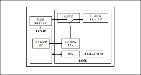
▲ STM32F4 Backup Domain
Most STM32s have a power regulator (some models do not) that powers all digital circuits except for the backup domain and standby circuit, with the regulator outputting a voltage of about 1.2 V.Run Mode:The regulator provides full power to the 1.2 V domain (core, memory, and digital peripherals).
Stop Mode:The regulator provides low power to the 1.2 V domain, retaining the contents of registers and internal SRAM.
Standby Mode:The regulator is powered down. Except for the standby circuit and backup domain, the contents of registers and SRAM will be lost.
STM32‘s working modes can usually be divided into four types: Run Mode, Sleep Mode, Stop Mode, Standby Mode. Depending on the type of STM32, the working modes can be further divided. For example, the STM32L low power series, the sleep mode can be further divided into: normal sleep mode and low power sleep mode.
-
Taking STM32F4 as an example:
-
Run Mode: Default mode;
-
Sleep Mode: Core stops, peripherals keep running
-
Stop Mode: All clocks stop
-
Standby Mode: 1.2 V domain powered down
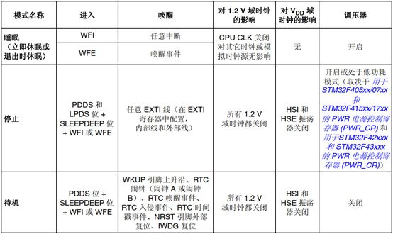
▲ Diagram of STM32 Sleep/Stop/Standby Modes
Key Points in STM32 Low Power Design
STM32 low power consumption is usually designed based on the actual situation of the project and the application scenario. The following are a few cases for illustration.
Case One:An engineer mentioned: Why can’t STM32F103 wake up from STOP mode via UART?
Analysis:This engineer misunderstood the low power wake-up mechanism: STM32 cannot be woken up directly from STOP mode by interrupt peripherals such as UART; it can only be woken up by EXTI external interrupts.
Solution:We can set the RX pin to EXTI mode before the MCU enters STOP and enable the corresponding interrupt to achieve this.
Case Two:An engineer mentioned: After entering low power mode, the actual power consumption is much greater than the ideal power consumption.
Analysis: The issue may be caused by the engineer directly calling the “stop mode” to enter low power mode, but some IOs have pull-up resistors that were not adjusted before entering low power, leading to excessive power consumption.
Solution:Before entering low power, adjust the states of used and unused IOs. For example, if there is an external pull-up, it can be configured as an analog input, etc.
Case Three:An engineer mentioned: Waking up STM32F103 via button, but UART does not work normally?
Analysis:It was found that the low power mode entered by the developer was standby mode, and after waking up, the UART peripheral was not initialized, causing the UART to not work normally. In standby mode, all peripherals are off, meaning all peripheral configurations revert to default values.
Solution:After waking up, reinitialize the UART (and all used) peripherals.
▼ Basic Knowledge of Power: Understand power voltage, types, and regulators;
▼ Low Power Modes: There are four types: Run Mode, Sleep Mode, Stop Mode, Standby Mode
▼ Key Points in Low Power Design: Avoid mistakes caused by basic principles.
Disclaimer:This article is sourced from STM32, and the copyright belongs to the original author. If there are copyright issues related to the work, please contact me for deletion.
‧‧‧‧‧‧‧‧‧‧‧‧‧‧‧‧ END ‧‧‧‧‧‧‧‧‧‧‧‧‧‧‧
Selected Summary | Directory | Search
The Advanced Path of Power Devices
Will Clang Compiler Replace GCC?
Follow the WeChat public account “strongerHuang”, reply “1024” in the background to see more exciting content.
Long press to go to the public account included in the picture to follow