● General Timer (TM2~TM5)
The general timer is managed by the chip and can perform up counting, down counting, or both simultaneously. Additionally, these timers have other functionalities: input capture, output compare, PWM, and single pulse.
● From Manual to Flow
The main module of the timer consists of a 16/32-bit counter and its related auto-reload registers. This counter can count in increasing, decreasing, or increasing/decreasing modes, and the clock can be divided by a prescaler. The counter, prescaler, and auto-reload register can be read and written through software, even while the counter is running.
The timer starts counting based on a specific clock, and once an overflow occurs, the corresponding flag is set to 1. We can continuously scan this flag to determine if the count has completed. If the interrupt function is enabled, then the overflow will also set the interrupt flag to 1.
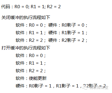
1. Shadow Register: Many chips have shadow registers, which are essentially buffer registers.
1) Disable buffering
The contents of the register are directly written into the buffer register, meaning all contents are passed into their respective shadow registers in the order of code execution. This method updates data according to the sequence of code execution.
2) Enable buffering
Values are assigned to registers one by one in the order of the code, and finally, through a switch, all contents are simultaneously passed into their respective shadow registers. This ensures that the data is updated simultaneously.
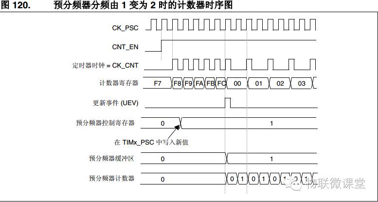
 2. Prescaler
The prescaler can divide the clock of the timer, and this register has buffering capabilities. Below is the timing diagram after enabling the prescaler buffering function. You can see that changing the prescaler value does not immediately affect the counting time, but rather at a certain moment when the buffer changes, it affects the counting time.
 Here, the event is the interrupt
3. Counting Modes
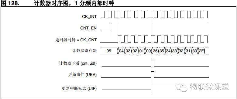
1) Up Counting
The counter counts from 0 to the auto-reload value and then generates an overflow event (if interrupts are enabled, an interrupt will occur here) and restarts counting from 0. Below is a timing diagram with an auto-reload value of 0x36.
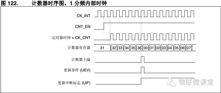
Note: At this point, one complete count is 0x36 + 1 time.
2) Down Counting
The counter counts down from the auto-reload value to 0, generating an overflow event (if interrupts are enabled, an interrupt will occur here) and restarts counting from the auto-reload value. Below is a timing diagram with an auto-reload value of 0x36.
Note: At this point, one complete count is 0x36 + 1 time.
3) Up/Down Counting (Center-Aligned Mode)
The counter counts from 0 to the auto-reload value – 1, generating an overflow event; then counts down from the auto-reload value to 1, generating another overflow event. After that, it starts counting from 0.
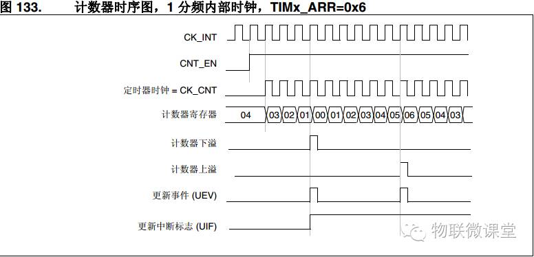
Note: The auto-reload value here is 6, and one complete count is 6 * 2 times.
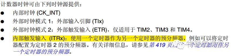
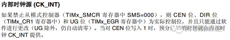
4. Clock Selection
5. Registers
TIMx_CR1 Control Register
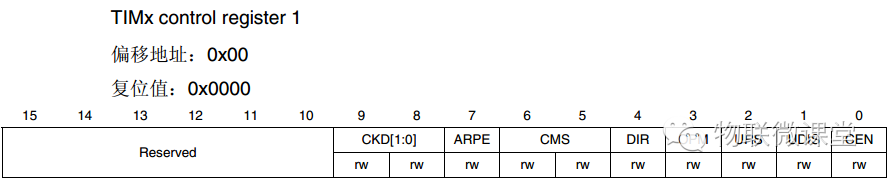
Set the register mode, auto-reload value buffering function, counter enable, interrupt enable
TIMx_SMCR Mode Register
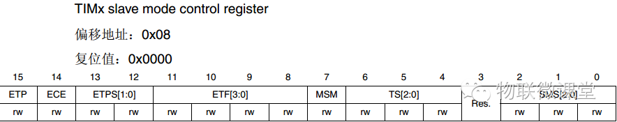
Select the timer clock source
TIMx_SR Status Register
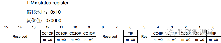
Some flags of the timer that can be used to determine if the timing is complete
TIMx_CNT Current Count Register
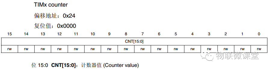
Current count value, can be read
TIMx_PSC Prescaler Register
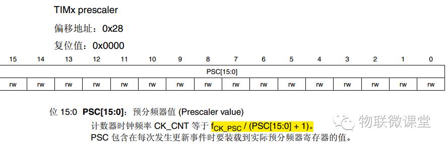
It is important to note the final obtained timing clock
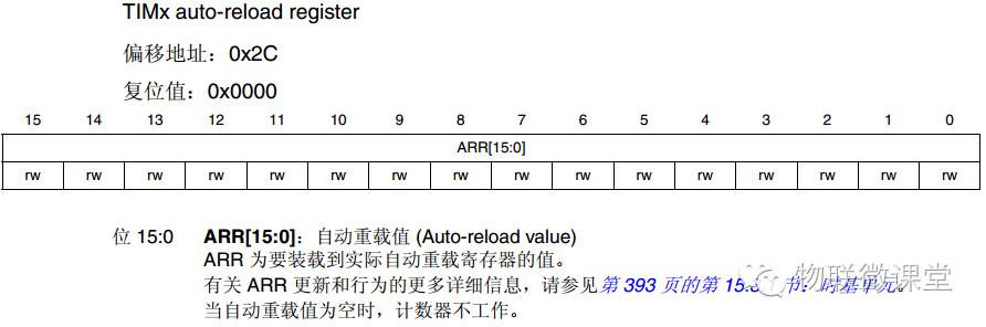
TIMx_ARR Auto-Reload Register
6. Timer Initialization Process
1) Enable the timer clock from RCC
2) Select the clock source
3) Set the prescaler coefficient
4) Enable or disable auto-reload buffering
5) Set the auto-reload value
6) Set the counting mode
7) Enable or disable interrupts
8) Configure timer interrupts
9) Enable the timer
● From Flow to Code
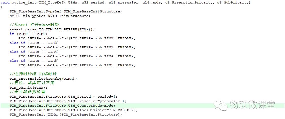
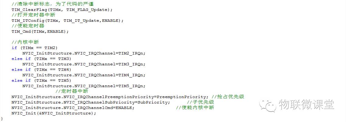
1. Timer Initialization
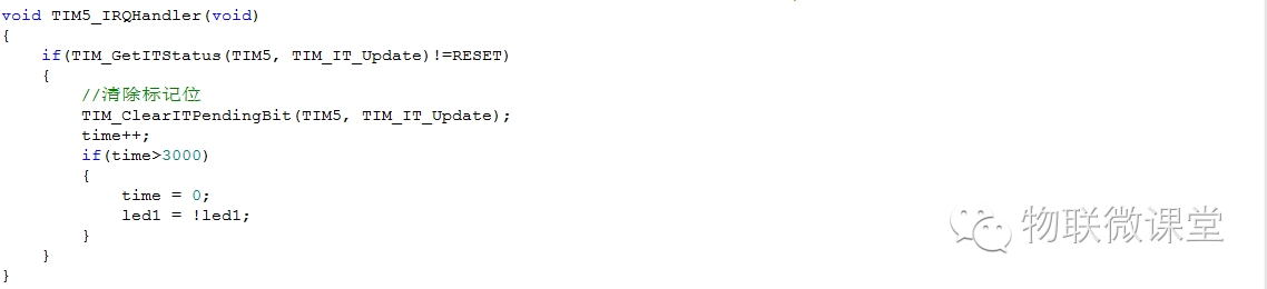
2. Interrupt Handler Function