01 STM32F373 Signal Acquisition and Control
1. Introduction
Due to the need to update a circuit board designed based on an old controller chip, this morning we will use the STM32F373 microcontroller to design a signal acquisition and control circuit board. First, we will design and produce it, and then proceed to software debugging.
AD\XQWF\2024\CLDesign\Ver2\CLMainF373.PcbDoc
2. Circuit Design
The core of the control circuit board is the STM32F373, which uses its ADC and DAC to interact with external control objects. External analog signals are filtered through resistors and capacitors before being input to the F373’s 16-bit ADC, which outputs a 12-bit DAC to control external circuits. Additionally, it communicates with the host computer via a USB interface. As an experimental circuit board, all wires are laid out on the TOP LAYER as much as possible. This makes it easier to obtain the test circuit board using the one-minute board-making method.
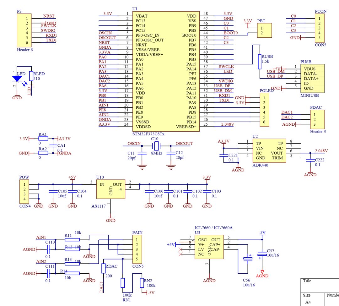
▲ Figure 1.2.1 Experimental Circuit Schematic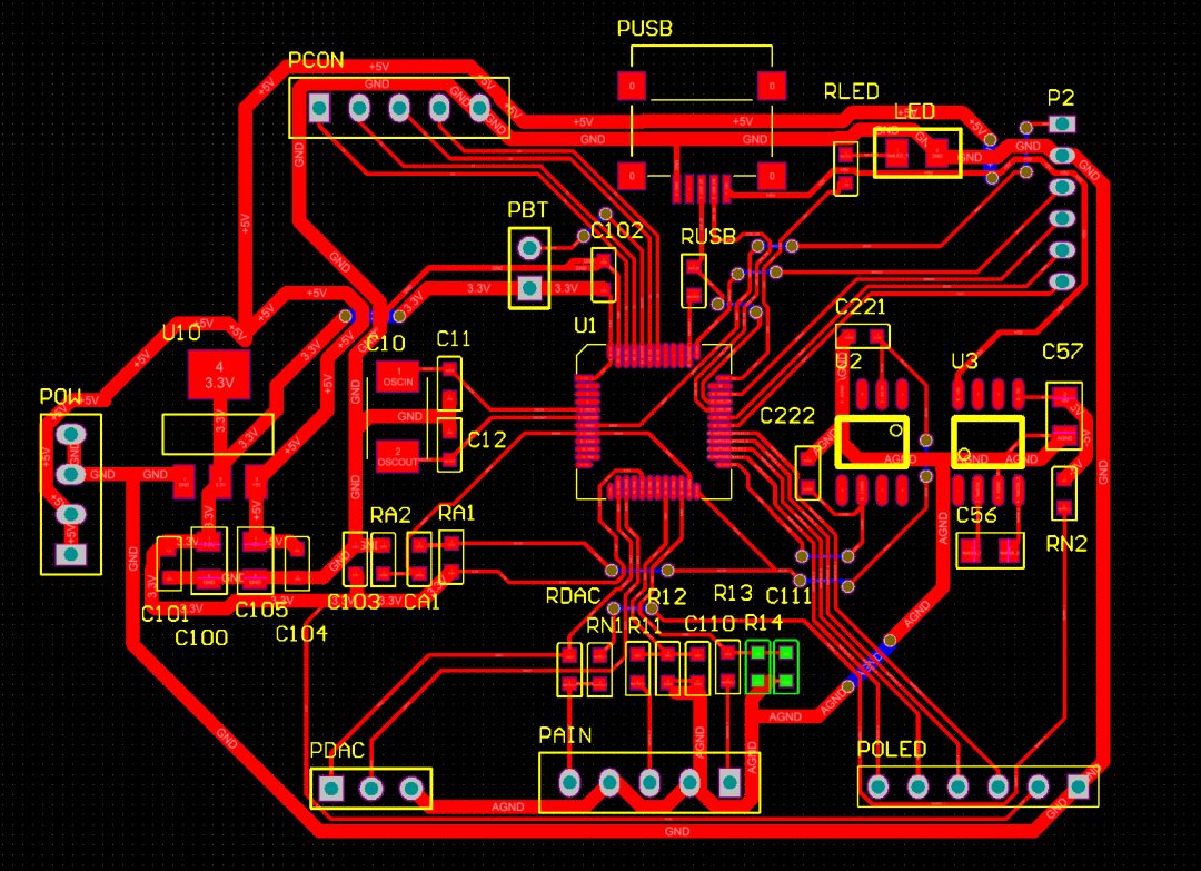
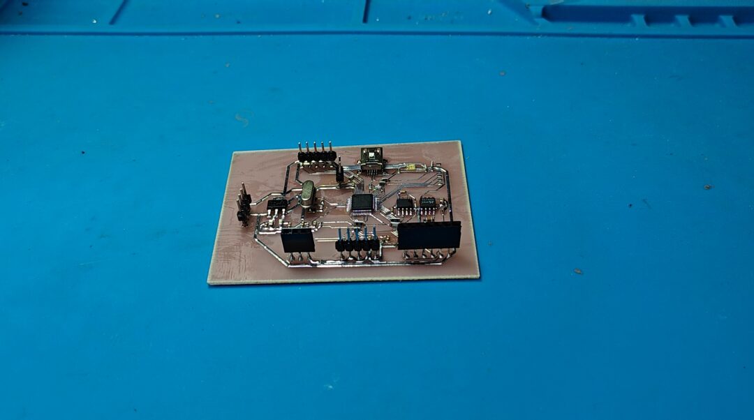
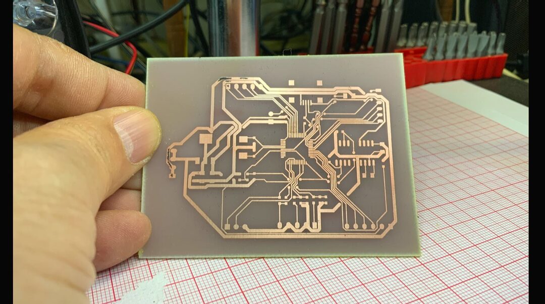
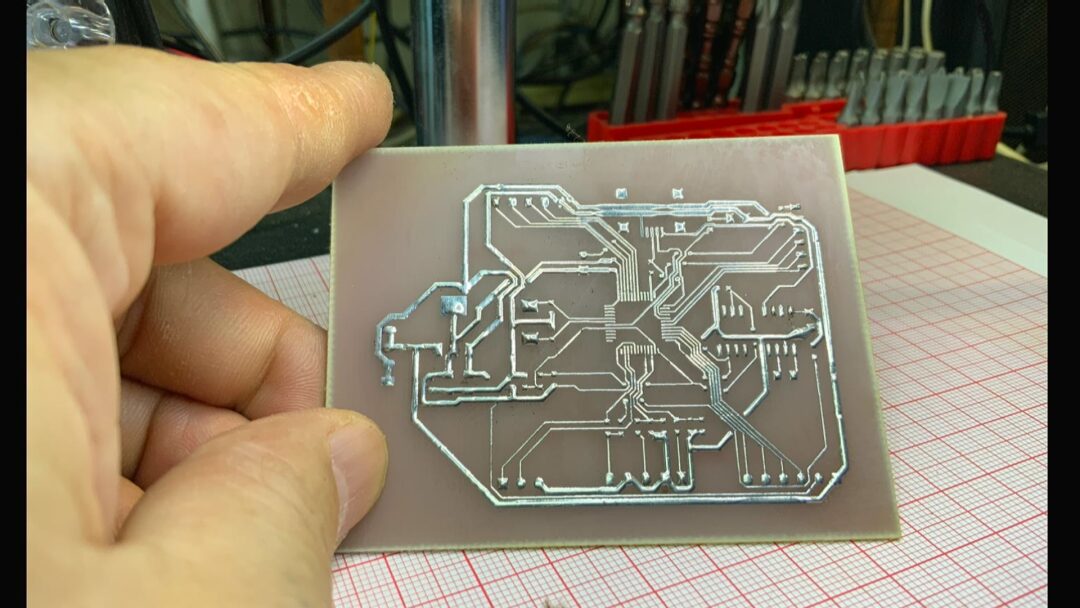
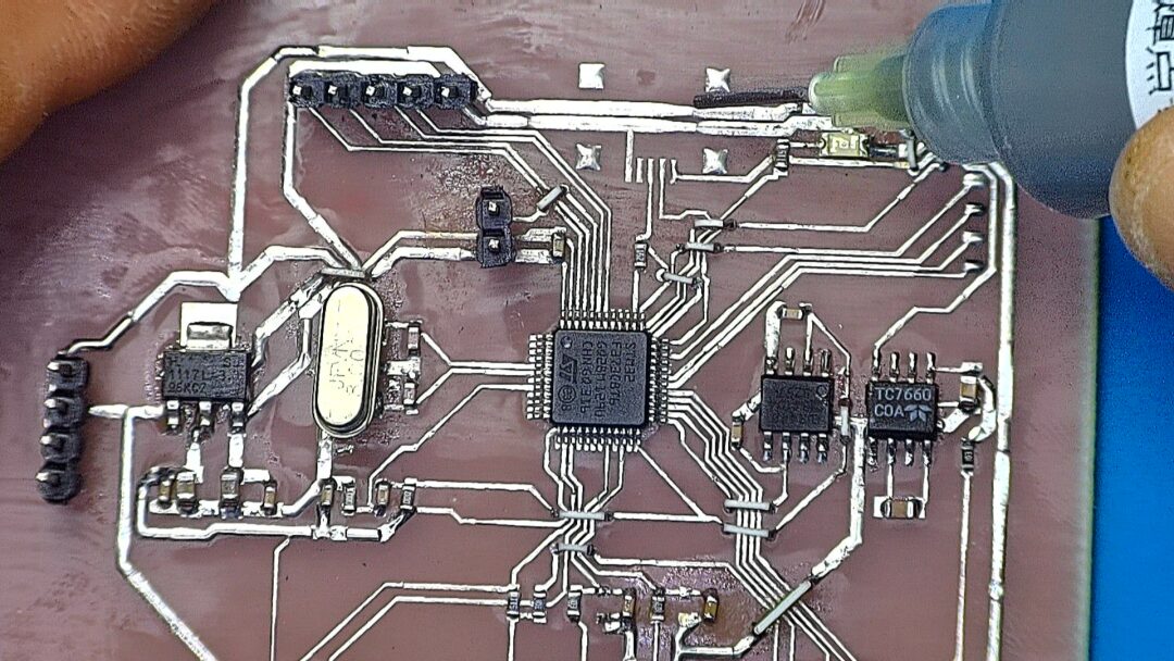
▲ Figure 1.2.2 Experimental Circuit PCBAfter one minute, we obtained the test circuit board, which was made perfectly. The closely spaced vias are where we will use 0-ohm resistors for flying leads later.
3. Soldering the Circuit
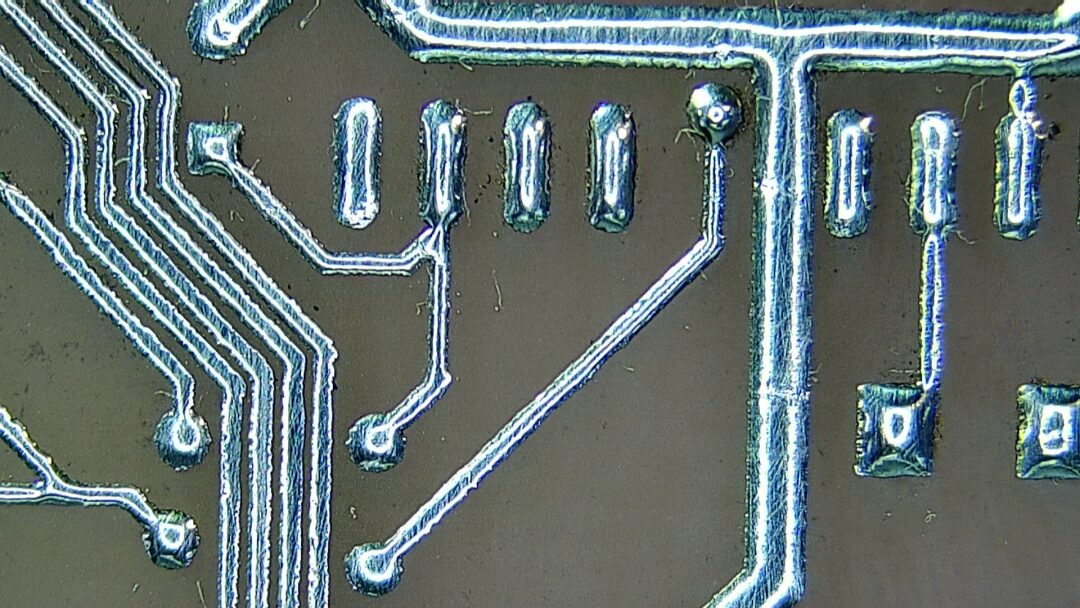
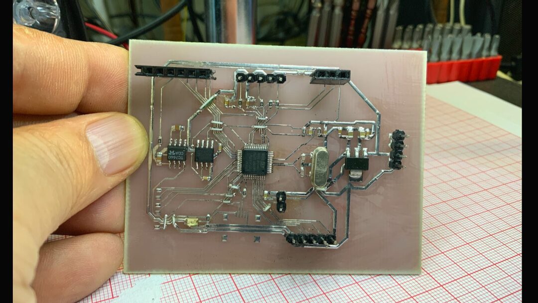
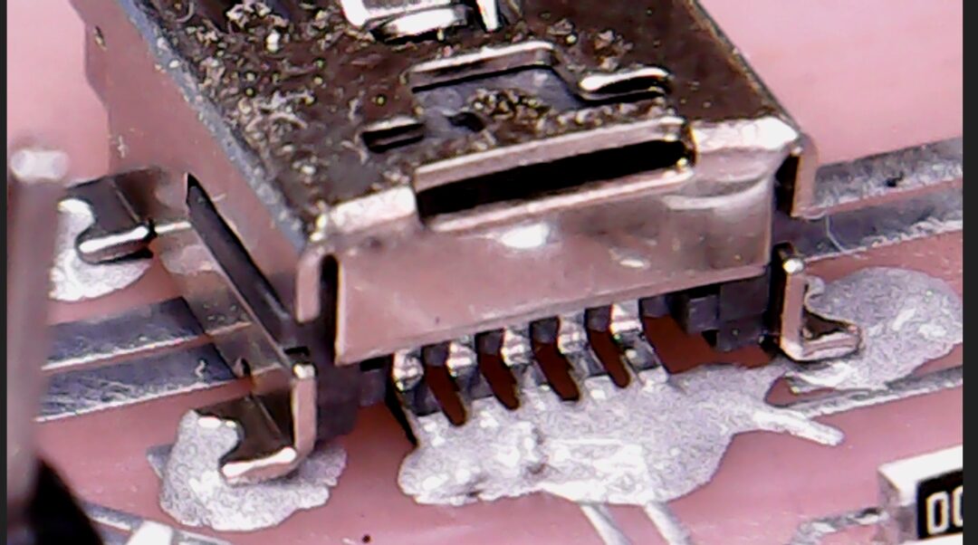
First, apply solder to the circuit board to facilitate subsequent soldering. After soldering, it is easier to check for defects on the circuit board. When soldering the circuit board, of course, careful inspection is required for the core TSOP48 packaged F373 microcontroller. It seems that there is a flying lead that hasn’t been soldered, which will be fixed later. On this circuit board, apart from the Mini USB interface, everything else has been soldered. Next, we will solder the USB socket. Solder paste is used for soldering. Heating requires patience. There was a bit too much solder paste at the pin, causing adjacent pins to stick together. Later, a soldering iron is used to remove the excess solder.
※ Conclusion ※
This article documents the production of a signal acquisition and control circuit board based on the STM32F373. Using the one-minute board-making method, we quickly produced the circuit board. Next, we will elaborate on its debugging process.