This article will explain how to DIY a biped robot. The hardware system of the biped robot mainly includes the microcontroller minimum system circuit, PWM circuit, indicator light circuit, independent key circuit, and power supply circuit. The main design requirements for this biped robot circuit are as follows:
1. Hardware Circuit Design
1.1 Microcontroller Minimum System Circuit
Create a new simulation project file and name it “TwoFootRobot”. The microcontroller minimum system circuit includes the microcontroller circuit, crystal oscillator circuit, and reset circuit. The microcontroller minimum system circuit is shown in Figure 1-1. The main function of the microcontroller minimum system circuit is to drive multiple servos via the IIC protocol.
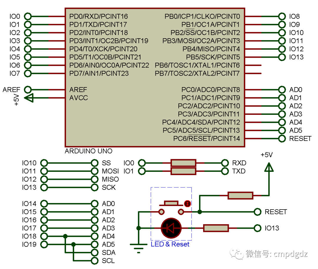
Figure 1-1 Microcontroller Minimum System
1.2 Power Supply Circuit
The voltage of commonly used lithium batteries is about 3.7V, while the power supply for the biped robot usually requires 3 lithium batteries in series to meet both voltage and size/weight requirements. The power supply circuit mainly consists of 3 voltage regulator circuits: the first voltage regulator circuit is composed of components like 7805, converting +11.1V voltage to +5V to power the microcontroller minimum system circuit, independent key circuit, and PWM circuit; the second voltage regulator circuit is composed of components like 7806, converting +11.1V voltage to +6V to power servo 0, servo 1, and servo 2; the third voltage regulator circuit is also composed of components like 7806, converting +11.1V voltage to +6V to power servo 3, servo 4, and servo 5. The power supply circuit drawn in Proteus software is shown in Figure 1-2.
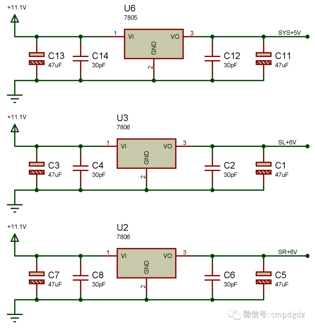
Figure 1-2 Power Supply Circuit
◎ Search for “7806” in the component library to find the 7806 voltage regulator chip.
1.3 PWM Circuit
The PWM circuit is mainly composed of the PCA9685 component, which can output a maximum of 16 PWM signals. The PWM circuit drawn in Proteus software is shown in Figure 1-3. Pin 27 of the PCA9685 component connects to IO18 of the Arduino microcontroller via the network labeled “SDA”, pin 26 connects to IO19 via the network labeled “SCL”, pins 23 and 25 are connected to the “GND” network, and pins 1, 2, 3, 4, 5, and 24 also connect to the “GND” network, which means they are set to low level. Pins 6 to 22 can be connected to different servos through different network labels.
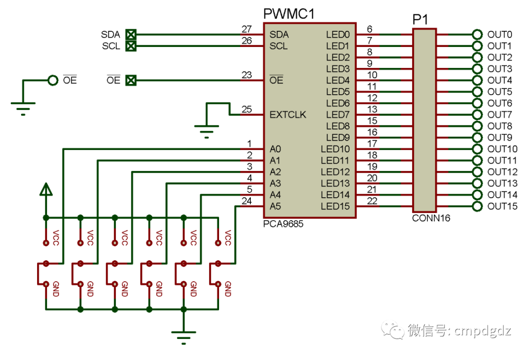
Figure 1-3 PWM Circuit
◎ Search for “PCA9685” in the component library to find the PCA9685 chip.
1.4 Servo Circuit
The servo circuit mainly consists of 6 servos. The servo circuit drawn in Proteus software is shown in Figure 1-4. Double-click on servo 0 to open the “Edit Component” dialog, set the Part Reference to SERVO0, Minimum Angle to -90.0, Maximum Angle to +90.0, Rotational Speed to 60, Minimum Control Pulse to 0.5m, and Maximum Control Pulse to 2.5m, as shown in Figure 1-5. Other servos can be set up similarly.
Servo SERVO0’s first pin connects to the first power supply circuit via the network labeled “+12V”, the second pin connects to PCA9685’s pin 6 via the network labeled “OUT0”, and the third pin connects to the “Ground” network; servo SERVO1’s first pin connects to the first power supply circuit via the network labeled “+12V”, the second pin connects to PCA9685’s pin 7 via the network labeled “OUT1”, and the third pin connects to the “Ground” network; servo SERVO2’s first pin connects to the first power supply circuit via the network labeled “+12V”, the second pin connects to PCA9685’s pin 8 via the network labeled “OUT2”, and the third pin connects to the “Ground” network; servo SERVO3’s first pin connects to the second power supply circuit via the network labeled “+12V”, the second pin connects to PCA9685’s pin 9 via the network labeled “OUT3”, and the third pin connects to the “Ground” network; servo SERVO4’s first pin connects to the second power supply circuit via the network labeled “+12V”, the second pin connects to PCA9685’s pin 10 via the network labeled “OUT4”, and the third pin connects to the “Ground” network; servo SERVO5’s first pin connects to the second power supply circuit via the network labeled “+12V”, the second pin connects to PCA9685’s pin 11 via the network labeled “OUT5”, and the third pin connects to the “Ground” network.
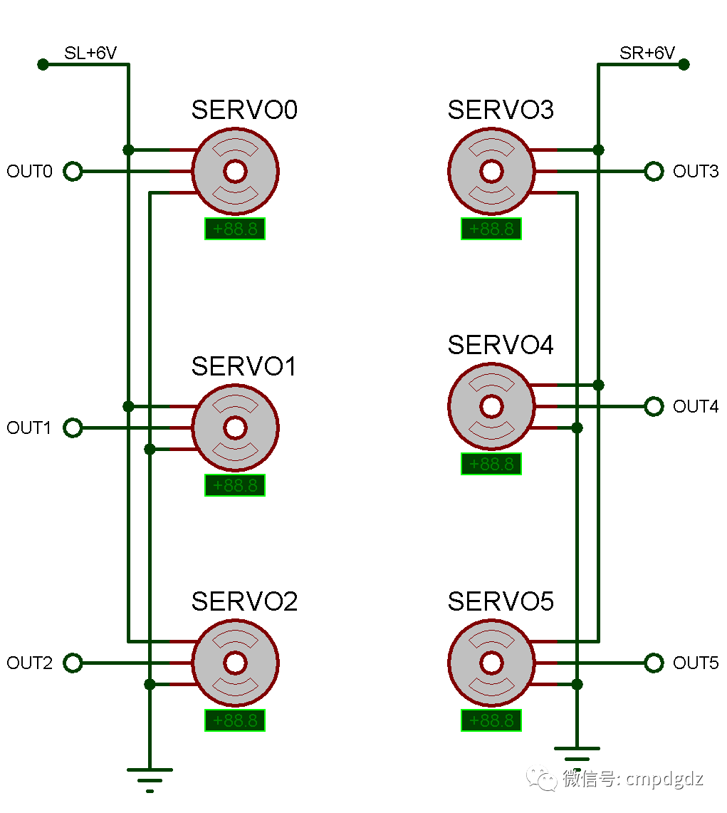
Figure 1-4 Servo Circuit
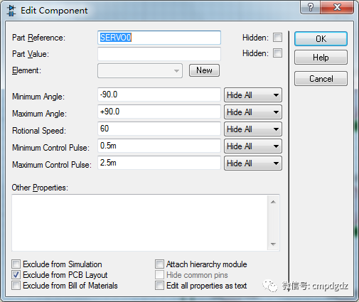
Figure 1-5 Servo Parameter Settings
1.5 Independent Key Circuit
The independent key circuit of the biped robot mainly consists of independent keys, capacitors, and resistors. The independent key circuit drawn in Proteus software is shown in Figure 1-6. The independent key circuit connects to the first power supply circuit via the network labeled “SYS+5V”. The independent key KEY1 connects to IO6 of the Arduino microcontroller via the network labeled “IO6”, and the independent key KEY2 connects to IO7 of the Arduino microcontroller via the network labeled “IO7”.
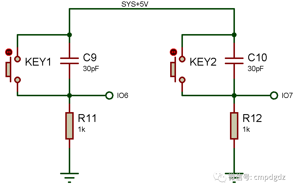
Figure 1-6 Independent Key Circuit
1.6 Indicator Light Circuit
The indicator light circuit of the biped robot mainly consists of light-emitting diodes and resistors. The indicator light circuit drawn in Proteus software is shown in Figure 5-2-6. The LED D2 connects to IO11 of the Arduino microcontroller via the network labeled “IO11”, and the LED D3 connects to IO12 of the Arduino microcontroller via the network labeled “IO12”.
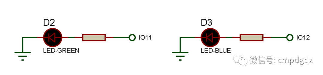
Figure 1-6 Indicator Light Circuit
2. Microcontroller Program Design
2.1 Main Program Functions
Enter the main programming interface of the biped robot. In the main function program, define the functions of the microcontroller pins, setting the Arduino microcontroller pins 13, 12, and 11 to output mode to drive the LEDs, and setting pins 6 and 7 to input mode to receive input signals from the independent keys. The specific program is as follows:
In the Loop() function, you can set the actions of the biped robot. When the independent key KEY2 is pressed, the LED D2 lights up, the LED D3 goes out, and the servos start to execute actions. When the independent key KEY1 is pressed, the LED D2 goes out, the LED D3 lights up, and the servos stop executing actions. The specific program is as follows:
delay(1000);
delay(1000);
delay(1000);
}
2.2 Complete Program
The complete program for the biped robot in main.ino is as follows:
delay(1000);
delay(1000);
delay(1000);
}
PWM Configuration Resource File Program:
}
PWM Configuration Header File:
#endif
Execute the command, and after successful compilation, the “VSM Studio Output” bar is shown in Figure 2-1.
 Figure 2-1 “VSM Studio Output” Bar
3. Overall Simulation Testing
Double-click on the Arduino microcontroller to open the “Edit Component” dialog, and you can see the path of the compiled file in the Program File, as shown in Figure 3-1.
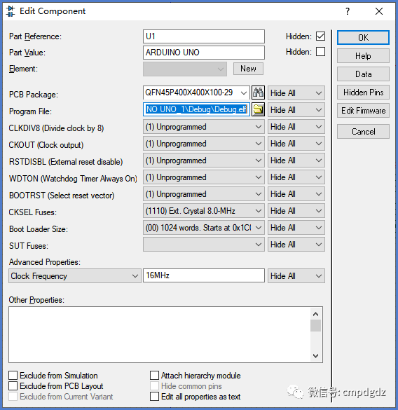
Figure 3-1 “Edit Component” Dialog
Execute the command to run the biped robot circuit simulation. In the initial state, the Arduino microcontroller’s indicator light is on, indicating that the Arduino microcontroller has started working normally. No LEDs in the indicator light circuit are lit. All 6 servos in the servo circuit are in the 0-degree position, as shown in Figure 3-2.
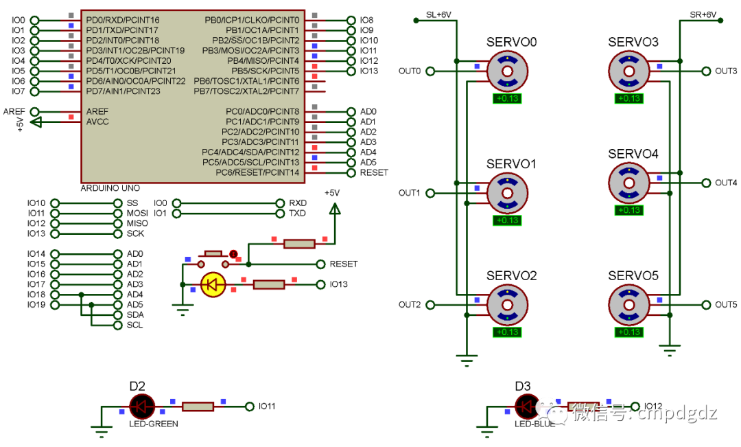
Figure 3-2 Simulation Result 1
Click on the independent key KEY1 in the biped robot circuit, and the blue LED in the indicator light circuit lights up while all 6 servos are in the -90-degree position, as shown in Figure 3-3.
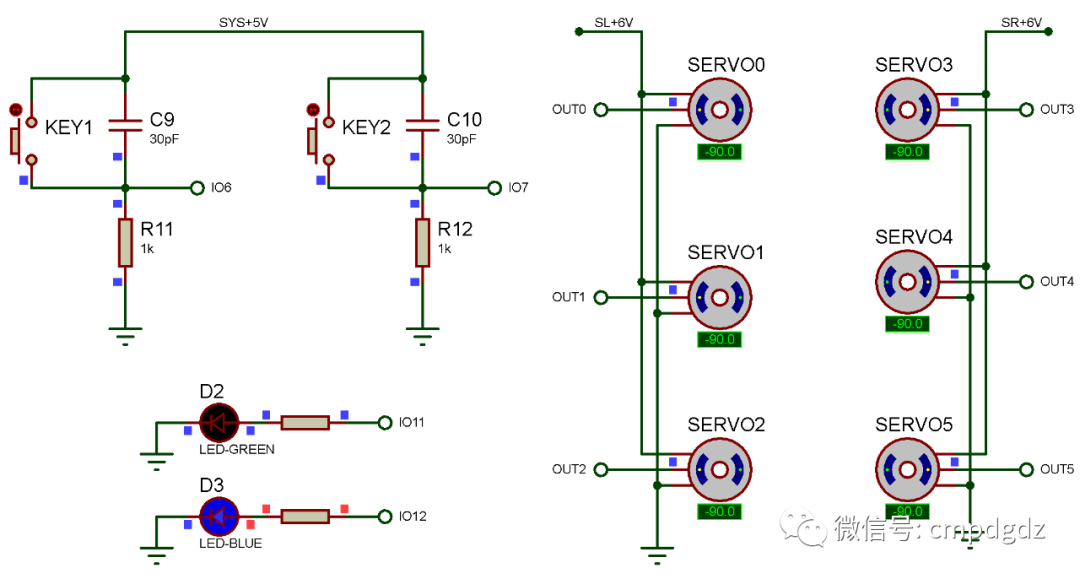
Figure 3-3 Simulation Result 2
Click on the independent key KEY2 in the biped robot circuit, and the green LED in the indicator light circuit lights up. The biped robot’s actions require the cooperation of 6 servos, executing a total of 10 poses in this example. When executing the first pose’s program, the specific program is as follows, where all 6 servos rotate to the 0-degree position, as shown in Figure 3-4.
delay(500);
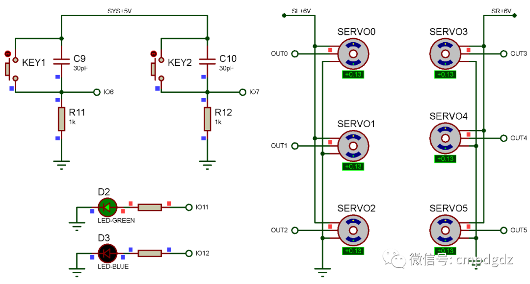
Figure 3-4 Simulation Result 3
When executing the second pose’s program, the specific program is as follows: SERVO0 rotates to -90 degrees, SERVO3 rotates to +90 degrees, SERVO1 rotates to 0 degrees, SERVO4 rotates to 0 degrees, SERVO2 rotates to 0 degrees, and SERVO5 rotates to 0 degrees, as shown in Figure 3-5.
delay(500);

Figure 3-5 Simulation Result 4
When executing the third pose’s program, the specific program is as follows: SERVO0 rotates to -90 degrees, SERVO3 rotates to +90 degrees, SERVO1 rotates to 0 degrees, SERVO4 rotates to 0 degrees, SERVO2 rotates to -90 degrees, and SERVO5 rotates to +90 degrees, as shown in Figure 3-6.
delay(500);
When executing the fourth pose’s program, the specific program is as follows: SERVO0 rotates to 0 degrees, SERVO3 rotates to +90 degrees, SERVO1 rotates to 0 degrees, SERVO4 rotates to 0 degrees, SERVO2 rotates to -90 degrees, and SERVO5 rotates to +90 degrees, as shown in Figure 3-7.
delay(500);

Figure 3-6 Simulation Result 5

Figure 3-7 Simulation Result 6
When executing the fifth pose’s program, the specific program is as follows: SERVO0 rotates to 0 degrees, SERVO3 rotates to +90 degrees, SERVO1 rotates to 0 degrees, SERVO4 rotates to 0 degrees, SERVO2 rotates to +90 degrees, and SERVO5 rotates to +90 degrees, as shown in Figure 3-8.
delay(500);
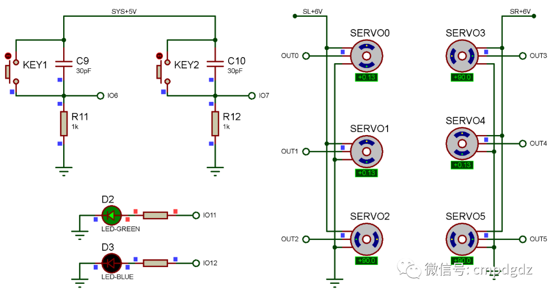
Figure 3-8 Simulation Result 7
When executing the sixth pose’s program, the specific program is as follows: SERVO0 rotates to +90 degrees, SERVO3 rotates to +90 degrees, SERVO1 rotates to 0 degrees, SERVO4 rotates to 0 degrees, SERVO2 rotates to +90 degrees, and SERVO5 rotates to +90 degrees, as shown in Figure 3-9.
delay(500);
When executing the seventh pose’s program, the specific program is as follows: SERVO0 rotates to +90 degrees, SERVO3 rotates to 0 degrees, SERVO1 rotates to 0 degrees, SERVO4 rotates to 0 degrees, SERVO2 rotates to +90 degrees, and SERVO5 rotates to +90 degrees, as shown in Figure 3-10.
delay(500);

Figure 3-9 Simulation Result 8

Figure 3-10 Simulation Result 9
When executing the eighth pose’s program, the specific program is as follows: SERVO0 rotates to +90 degrees, SERVO3 rotates to 0 degrees, SERVO1 rotates to 0 degrees, SERVO4 rotates to 0 degrees, SERVO2 rotates to +90 degrees, and SERVO5 rotates to -90 degrees, as shown in Figure 3-11.
delay(500);
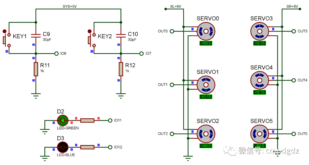
Figure 3-11 Simulation Result 10
When executing the ninth pose’s program, the specific program is as follows: SERVO0 rotates to +90 degrees, SERVO3 rotates to -90 degrees, SERVO1 rotates to 0 degrees, SERVO4 rotates to 0 degrees, SERVO2 rotates to +90 degrees, and SERVO5 rotates to -90 degrees, as shown in Figure 3-12.
delay(500);
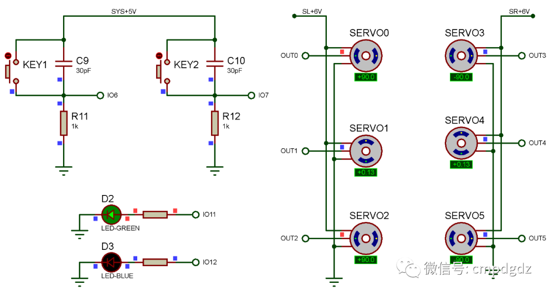
Figure 3-12 Simulation Result 11
When executing the tenth pose’s program, the specific program is as follows: SERVO0 rotates to 0 degrees, SERVO3 rotates to 0 degrees, SERVO1 rotates to 0 degrees, SERVO4 rotates to 0 degrees, SERVO2 rotates to 0 degrees, and SERVO5 rotates to 0 degrees, as shown in Figure 3-13.
delay(500);
All ten poses will loop to complete the forward rolling action of the biped robot. The forward rolling action programmed in this section may not be universal; readers should write the pose programs based on the actual servo assembly of the biped robot, following the principle of converting actions into several static poses.
◎ Scan the QR code below to watch the simulation video of the biped robot’s forward rolling action.

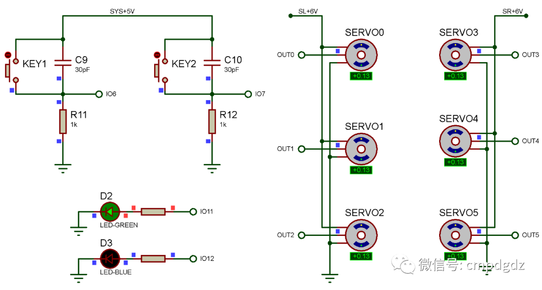
Figure 3-13 Simulation Result 12
4. Design Summary
The biped robot circuit consists of the power supply circuit, microcontroller minimum system circuit, indicator light circuit, servo drive circuit, and PWM circuit, which basically meet the requirements. Readers can DIY a dancing robot based on the design method of this example. In practical applications, the power supply circuit composed of LM7806 should not power multiple servos; otherwise, it may cause damage to the LM7806 and other adverse consequences. When writing the biped robot’s action programs, it is necessary to add a certain delay during pose transitions, as servos require time to rotate to the specified angle.