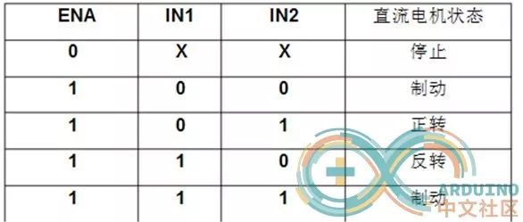
Based on Arduino, this tutorial will guide you through the process of creating your own Bluetooth car, familiarizing you with the entire project workflow.
First, here are the tools you will need:
1. Arduino UNO R3 x1
2. L298N Motor Driver Module x1
3. HC06 Bluetooth Module x1
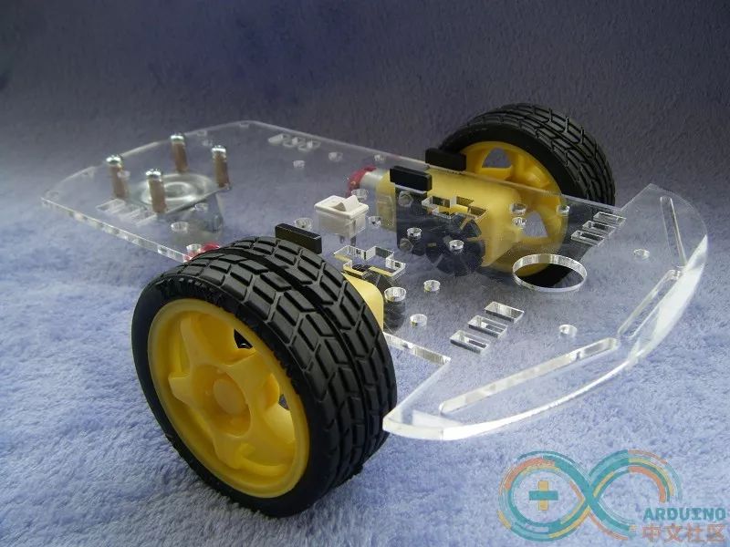
4. Car Chassis x1
5. 12V Power Supply (7~9V) x1
6. Several Jumper Wires
7. Bluetooth Remote Control App
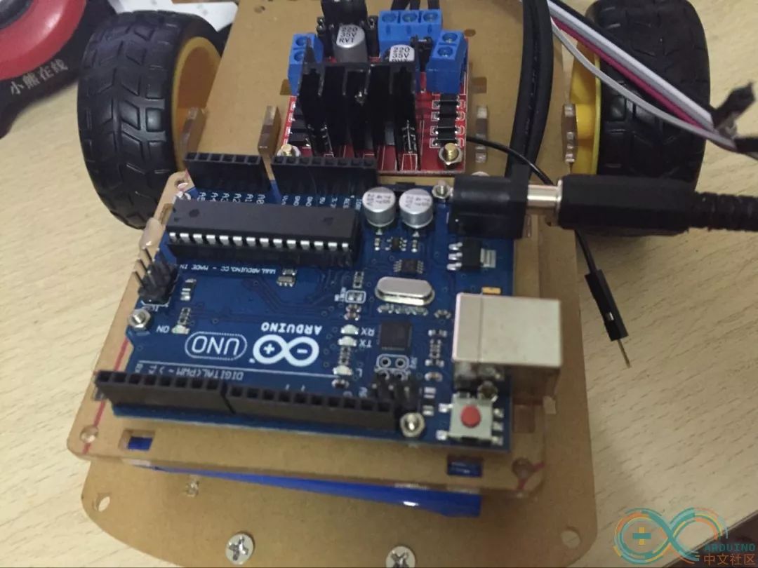
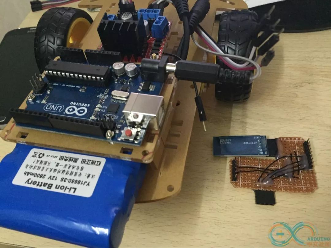
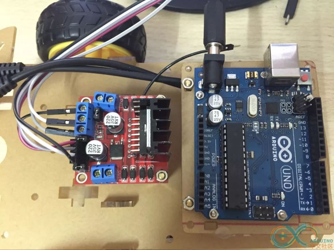
Note: 1. The L298N Motor Driver Module is simple and easy to understand.
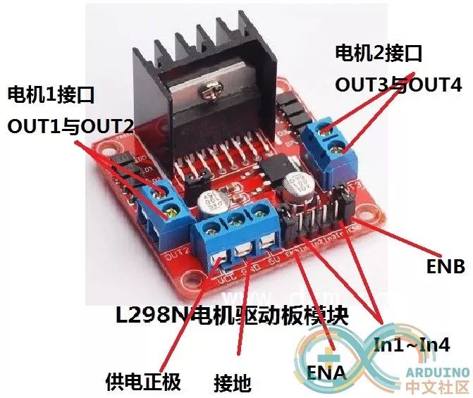
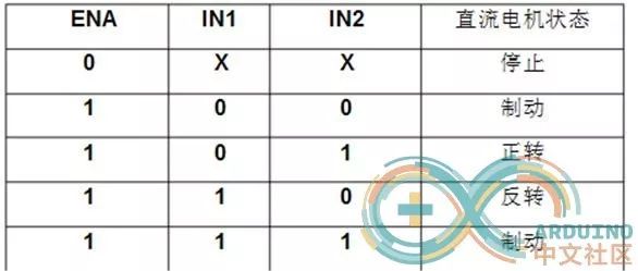
2. Bluetooth Module HC06
Connect the Bluetooth module to the power supply, then connect the Tx pin of the Bluetooth to the Rx pin of the development board. Leave the Bluetooth Rx pin unconnected, as there is no need to send data from the development board to the mobile app. Once powered correctly, we can connect to the Bluetooth using our phone and pair it. The password is usually “1234” or “0000”. After entering the password, pairing is successful.
3. Power Supply: I used a 12V 18650 battery.
4. Car Chassis
5. Principle of the Bluetooth Car: The app sets the code –> The phone sends the code via Bluetooth –> HC06 receives the code and sends it to the Arduino board –> The board parses the code –> Controls the motor
5. Testing Program for the App and Bluetooth Module.
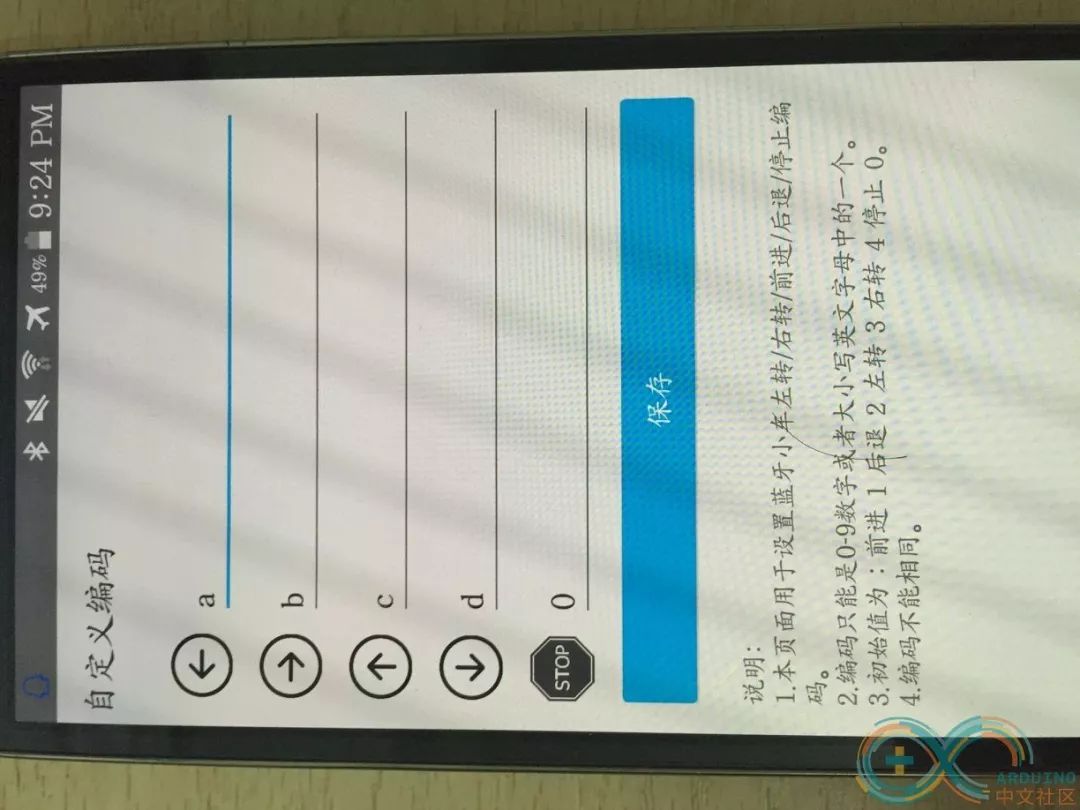
After opening the app, a prompt will automatically appear asking to turn on the phone’s Bluetooth. You will see four directional arrows and a stop button, which are used to control the car’s movement. Before performing these operations, ensure you are connected to the Bluetooth module HC06 of the Bluetooth car. Click on the icon in the lower right corner that looks like a nut to bring up the following image:
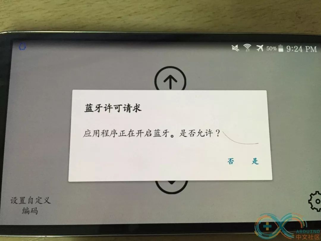
(App Download Linkhttp://android.myapp.com/myapp/d … ty.app.bluetoothcar)
If the above image does not appear, please click to search for Bluetooth devices. You should see an HC06. If not, make sure your Bluetooth module’s power is connected correctly. Once you see HC06, click on it. If it is your first pairing, you will need to enter the password: default is 0000 or 1234. If you have paired before, it will connect automatically. The Bluetooth car can move forward, backward, turn left, turn right, and stop, all represented by a specific code. In my app, I have set the default codes as: Forward 3, Backward 4, Left 1, Right 2, Stop 0. You can also customize the codes by clicking the lower left corner to enter the settings page.
Upload the following test code to the Arduino UNO R3 board:
void setup() { // put your setup code here, to run once: Serial.begin(9600);}void loop() { // put your main code here, to run repeatedly: if(Serial.available()>0){ char ch = Serial.read(); if(ch == '1'){ // Forward Serial.println("up"); }else if(ch == '2'){ // Backward Serial.println("back"); }else if(ch == '3'){ // Turn Left Serial.println("left"); }else if(ch == '4'){ // Turn Right Serial.println("right"); }else if(ch=='0'){ // Stop Serial.println("stop"); }else{ // Other codes Serial.println(ch); } }}Then you can use the built-in serial monitor of the Arduino IDE to check the output.
That concludes the tutorial for the app side and testing code, which is not very difficult. Once you have the codes, the remaining task is for the Arduino to operate the motors based on these codes.
Specific circuit connections: Step 1: Connect the 12V 18650 rechargeable battery to the +12V and GND of the L298N motor driver module. The +5V output powers the Arduino UNO R3 board. Some may say that if the motor and board are powered by the same source, the motor’s operation might affect the board’s power supply. I have not encountered this issue during my tests. This may be because the board’s power consumption is not very high, and the 12V battery has sufficient capacity to avoid power shortage issues. Step 2: Connect the left motor to OUT3 and OUT4, and the right motor to OUT1 and OUT2. Step 3: Connect the IN control pins of the L298N to the Arduino board. IN1 connects to pin 6, IN2 connects to pin 7, IN3 connects to pin 4, and IN4 connects to pin 5.
Next, you will need to test and debug: 1. Test whether the motor can work. Method: Hardware test, connect IN1 to Arduino board +5V and IN2 to GND. You can observe the direction; if it is reversed, simply swap the connections.
2. The main event, let’s get to the final code:
/* Date: 2016/11/05 Function: Bluetooth Car Program Author: Microcontroller Beginner */#define IN1 6 // Right wheel #define IN2 7 #define IN3 4 // Left wheel #define IN4 5 #define LEFT '3' // Left turn code #define RIGHT '4' // Right turn code #define GO '1' // Forward code #define BACK '2' // Backward code #define STOP '0' // Stop code char left_code = '1'; void setup() { // put your setup code here, to run once: Serial.begin(9600); pinMode(IN1,OUTPUT); pinMode(IN2,OUTPUT); pinMode(IN3,OUTPUT); pinMode(IN4,OUTPUT); initCar();} void loop() { // put your main code here, to run repeatedly: if(Serial.available()>0){ char ch = Serial.read(); if(ch == GO){ // Forward go(); }else if(ch == BACK){ // Backward back(); }else if(ch == LEFT){ // Left turn turnLeft(); }else if(ch == RIGHT){ // Right turn turnRight(); }else if(ch=='0'){ // Stop stopCar(); } }} void initCar(){ // Defaults to low level, stopped state digitalWrite(IN1,LOW); digitalWrite(IN2,LOW); digitalWrite(IN3,LOW); digitalWrite(IN4,LOW);}/*** Left turn */void turnLeft(){ digitalWrite(IN1,HIGH); digitalWrite(IN2,LOW); // Right wheel moves forward digitalWrite(IN3,LOW); digitalWrite(IN4,LOW); // Left wheel does not move}/*** Right turn */void turnRight(){ digitalWrite(IN1,LOW); digitalWrite(IN2,LOW); // Right wheel does not move digitalWrite(IN3,HIGH); digitalWrite(IN4,LOW); // Left wheel moves forward}/*** Forward */void go(){ digitalWrite(IN1,HIGH); digitalWrite(IN2,LOW); // Right wheel moves forward digitalWrite(IN3,HIGH); digitalWrite(IN4,LOW); // Left wheel moves forward}/*** Backward */void back(){ digitalWrite(IN1,LOW); digitalWrite(IN2,HIGH); // Right wheel moves backward digitalWrite(IN3,LOW); digitalWrite(IN4,HIGH); // Left wheel moves backward}/*** Stop */void stopCar(){ initCar();}The Arduino tutorial concludes here. I hope everyone can create a satisfactory project and realize their DIY ambitions.
Text: Li Qinggen Photos: Tao Dongpeng
Layout: Lu Le
Review: Lu Jiangtao, Cao Zheyue
