
In this article, we will learn how to use the DS1302 by leveraging library functions to drive the DS1302 and obtain time data.
The DS1302 is a widely used RTC chip, introduced by DALLAS, which is a trickle-charged clock chip that contains a real-time clock/calendar and 31 bytes of static RAM, communicating with microcontrollers via a simple serial interface.
-
The real-time clock can compute seconds, minutes, hours, days, dates, weeks, months, and years before the year 2100, along with leap year adjustments.
-
31X8 bits of temporary data storage RAM.
-
Serial I/O mode minimizes pin count.
-
Wide operating voltage range of 2.0-5.5V.
-
Two transfer modes for reading/writing clock or RAM data: single-byte transfer and multi-byte transfer.
-
Dual power management for main and backup power supplies.
-
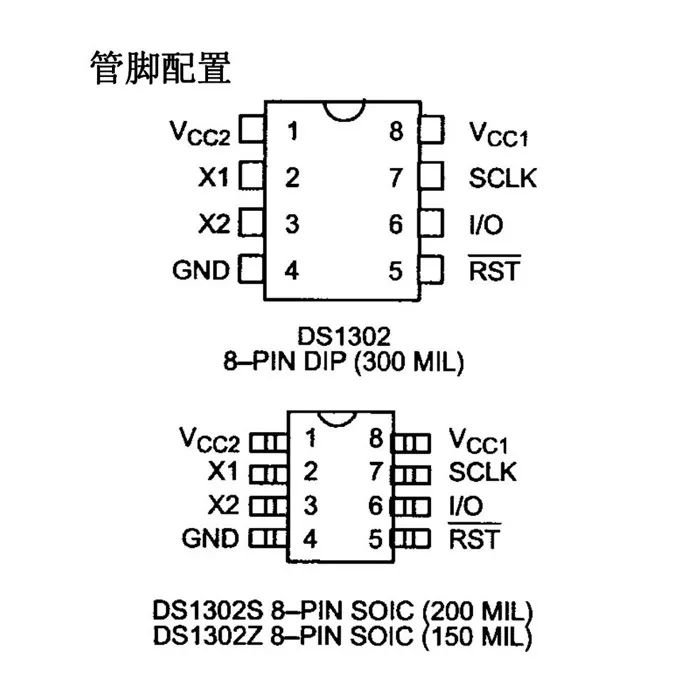
X1, X2: 32.768KHz crystal oscillator pins
-
GND: Ground
-
#RST: Reset pin
-
I/O: Data input/output pin
-
SCLK: Serial clock pin
-
Vcc1: Backup power pin, usually connected to a button cell
-
Vcc2: Main power pin
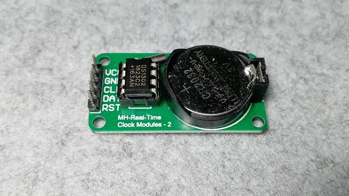
The DS1302 module we are using has integrated the DS1302 clock chip, crystal oscillator, and button cell into a small board:
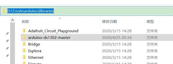
This article uses the DS1302 library to drive the DS1302, eliminating the need to worry about the read/write timing and internal register information of the DS1302. There are many driver libraries available for the DS1302; here we will use the library provided by msparks, which can be downloaded from GitHub (https://github.com/msparks/arduino-ds1302).
Unzip the downloaded library and copy it into the libraries folder in the Arduino IDE installation directory.
-
Uno R3 Development Board
-
USB Data Cable
-
Male to Female Dupont Wires
-
DS1302 Module
1. Build the circuit according to the schematic.
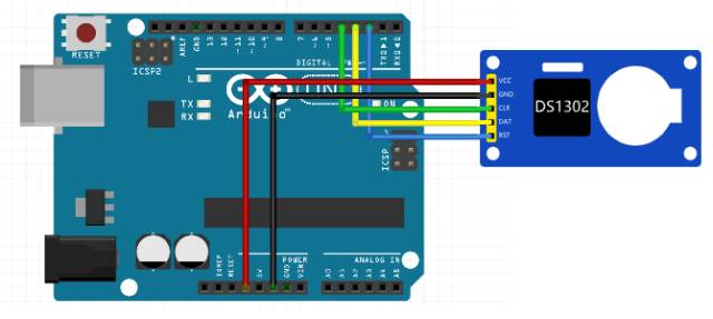
Connect the VCC and GND of the DS1302 module to the 3.3V and GND of the Uno development board. The CLK, DAT, and RST of the DS1302 module correspond to pins 4, 3, and 2 of the Uno development board.
The experimental schematic is shown below:
The physical connection diagram is shown below:
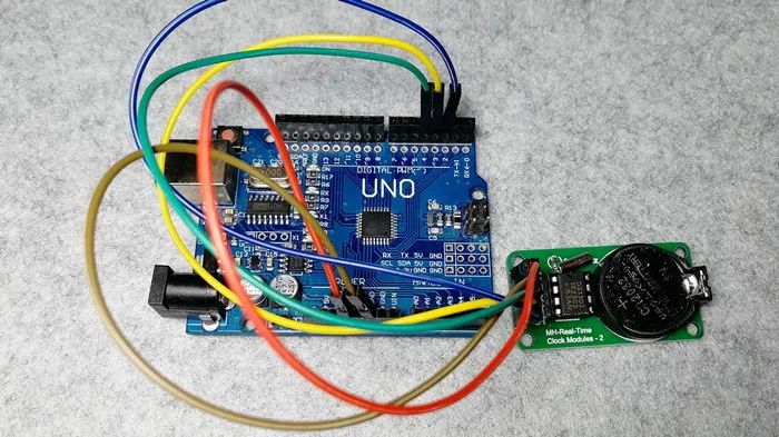
2. Create a sketch, copy the following code to replace the auto-generated code, and save it.
#include <DS1302.h>

DS1302 rtc(2, 3, 4); // Corresponding to DS1302's RST, DAT, CLK

void initRTCTime(void)// Initialize RTC time
{
  rtc.writeProtect(false); // Disable write protection
  rtc.halt(false); // Clear clock stop flag
  Time t(2020, 4, 25, 21, 50, 50, 7); // Create time object; last parameter is week data, Sunday is 1, Monday is 2, and so on
  rtc.time(t);// Set time data to DS1302
}

void printTime()// Print time data
{
  Time tim = rtc.time(); // Get time data from DS1302
  char buf[50];
  snprintf(buf, sizeof(buf), "%04d-%02d-%02d %02d:%02d:%02d",
           tim.yr, tim.mon, tim.date,
           tim.hr, tim.min, tim.sec);

  Serial.println(buf);
}

void setup() {
  Serial.begin(9600);

  // New module needs to set the current time once,
  // After downloading, disable this function to download again, otherwise time data will be initialized every time powered on
  initRTCTime();
}

void loop() {
  printTime();
  delay(1000);
}
3. Connect the development board, set the corresponding port number and board type, and download the program.
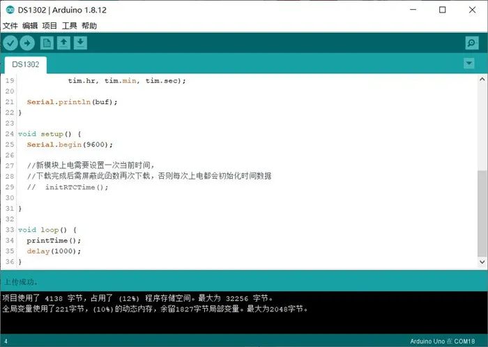
Open the Serial Monitor, set the baud rate to 9600 as in the program, and you will see the output time data.
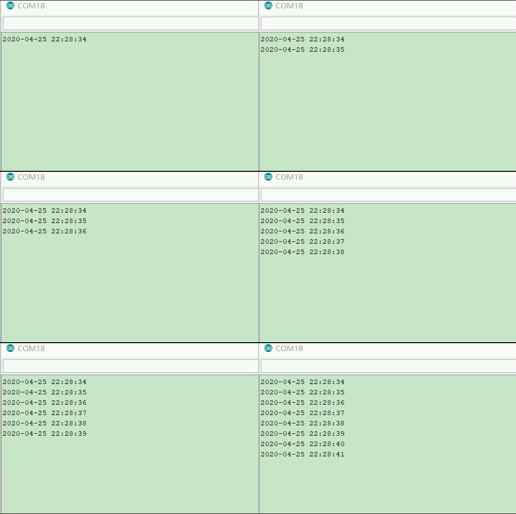
Since our DS1302 module has a button cell as a backup battery, the timekeeping will not stop even when the main power Vcc is cut off. You can disconnect the power from the development board, wait for a while, and then power it back on; upon opening the Serial Monitor again, you will see that the time has not stopped.
Summary of Arduino Basics
Arduino Enhancement Article 21—RFID Module Access Control Design
Basic Graphics Drawing with Processing
Follow the public account “TonyCode”, reply in the background “Enhancement” to obtain the code resources in this article.

Reply “1024” in the background to get 1000G of learning materials
