Standard Structure of PLC Alarm Programs
- Standardized Programming: Use abbreviated variable names, and describe functions accurately in comments, such as the input interface variable name Active (bool type, comment as Alarm Message), CBFW (bool type, comment as Control Bit Warning/Fault (0=Warning /1=Fault)).
- Block Title and Detailed Description: The block title is limited to a one-line brief description of the function, while the detailed description includes new block identification (New), last editor (Last Modification), modification date (Modified On), and copyright information (Copyright).
- Alarm Function Block Structure: Includes modules for loading signals into the function, setting new and old alarms, resetting alarms, alarm output to monitoring, fault collection, and prompts.
- Common Alarm Function Structured Variables: Operations include triggering alarms, confirming alarms, and silencing alarms.
Motor Overload Alarm Case
- Control Requirements: Two motors start and stop sequentially, each with a running indicator (green light) and overload alarm indicator (red light). If one motor is overloaded, both stop immediately, and the overload motor’s alarm light flashes at a frequency of 1Hz until the stop button is pressed.
- Program Logic:
- Program start section: Control Q1.0 (coil), Q1.2 (coil), and timer S_ODT (3S) through contacts I1.0 (normally open), I1.2 (normally closed).
- Main control section for overload: M2.0 (normally open), Q1.0 (normally open) control Q1.1 (coil), Q1.3 (coil).
- Motor start 3-second limit section: I1.2 (normally open), I1.0 (normally closed) control M2.1 (coil) and timer S_ODT (3S).
- Signal source control section: M2.2 (normally open), Q1.0 (normally closed) control M2.3 (coil).
- Overload protection flashing section: I1.4 (normally open), I1.2 (normally closed) control M2.5 (coil), combined with M0.5 (normally open) control Q1.4 (coil) to achieve the first motor overload flashing; I1.5 (normally open), I1.3 (normally closed) control M2.6 (coil), combined with M0.5 (normally open) control Q1.5 (coil) to achieve the second motor overload flashing.
Sensor Fault Alarm Case
- SM338 Module SF Alarm Handling: After the device cuts off the main power with the emergency stop, the SM338 module’s red light alarms, and the HMI displays data anomalies. The inspection steps include confirming power reset, hardware online diagnostics, replacing the module, and re-downloading hardware and user programs, ultimately restoring data.
- Fault Cause: Abnormal power outage caused CPU parameter loss, restored after re-downloading the program.
Siemens S7-1200 Alarm Program Case
- FB Block ALARMB Interface: ENA (trigger bit, rising edge), INFO1 – 3 (strings), SEP (separator), PV (embedded process value), outputs include Writing (WINCC alarm trigger signal), MSG (WINCC alarm information text), and auxiliary variables (e.g., BUFF array, upper limit 80).
- Program Logic: When ENA arrives, organize the alarm string to the free position in BUFF; when BUFF has data, execute FIFO to send to MSG and trigger Writing. After WINCC receives it, the PLC cancels sending, and after a delay, sends the next one.
- WINCC Configuration: Establish alarm entries, with the trigger signal as ALMB_DB.Writing and alarm information as ALMB_DB.MSG.
Illustration Description
Figure 1: PLC Ladder Diagram (Motor Overload Alarm Logic)
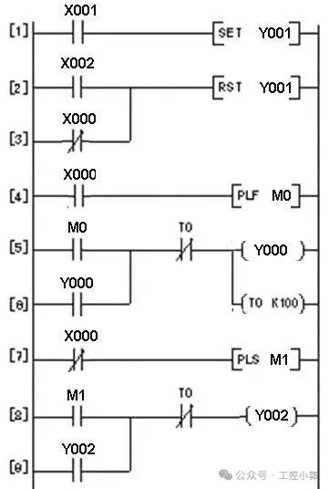
This ladder diagram contains 9 lines of logic, using input relays X000-X002, output relays Y000-Y002, and timer T0 to achieve motor overload detection and alarm triggering functions. The 5th line controls the Y000 coil through the normally open contact of M0 and the normally closed contact of T0, implementing the alarm light flashing logic.
Figure 2: PLC Wiring Diagram (Alarm System Hardware Connection)
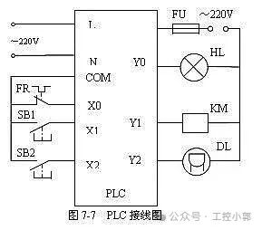
The diagram shows the connection relationship between the PLC main module and input/output terminals. The left input circuit includes thermal relay FR, push buttons SB1-SB2, and the right output circuit drives indicator light HL, contactor KM, and solenoid valve DL, reflecting a typical alarm system hardware architecture.
Figure 3: Electrical Control Circuit Diagram (Main Circuit and Control Circuit)
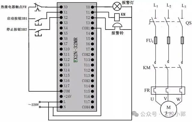
The left side is the PLC control circuit (model EX2N-32MR), and the right side is the main circuit (including three-phase asynchronous motor M). The control circuit connects external sensors through terminals X0-X17, and outputs Y0-Y17 drive alarm lights and contactors, achieving overload protection and alarm functions.
Figure 4: Fault Handling Logic Flowchart (Motor Overload Shutdown Process)
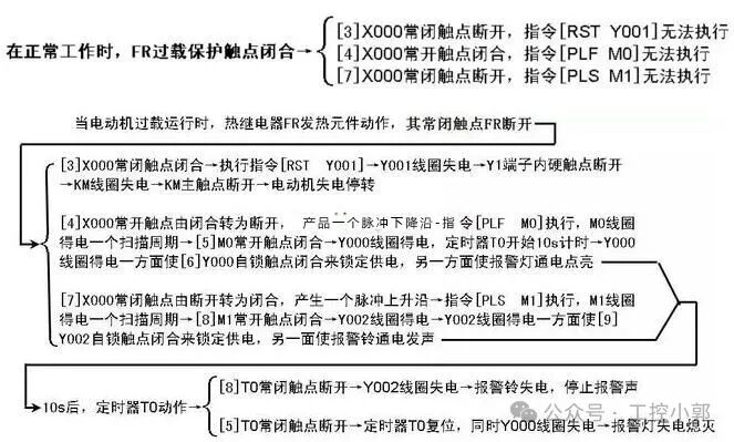
This flowchart details the control logic when the motor is overloaded: thermal relay FR acts → X000 contact state changes → M0/M1 pulse command triggers → Y000/Y002 coils are energized → alarm light turns on and alarm sounds → after 10 seconds, T0 acts to reset the alarm.
Practical Skills Supplement
- Ladder Diagram Drawing Specifications: Input relays (X) and output relays (Y) should be arranged by functional areas, such as concentrating overload detection-related contacts to avoid crossed wiring.
- Wiring Precautions: Sensor signal lines must use shielded cables, grounded at one end to reduce electromagnetic interference that causes false alarms (refer to the terminal wiring method in Figure 2).
- Troubleshooting Mnemonic: “First check the indicator light flashing frequency, then measure the terminal voltage, monitor the M state in the ladder diagram” — By checking the T0 timer state in the flowchart (whether it is stuck at the 10-second timing), you can quickly locate the cause of the alarm not resetting.
Practical Experience Supplement (Purely Practical, Avoid AI Tone)
1. Pitfalls Encountered During On-Site Debugging
-
Do not blindly trust module diagnostic information
-
Last time at an automotive factory, the SM338 module reported an SF red light, and online diagnostics showed “external sensor fault”. After replacing the sensor, the alarm persisted. Later, upon opening the metal hose, it was found that the shielded cable was crushed, with half of the copper wire broken — such physical damage cannot be detected by the module! (This pitfall is not shown in the flowchart in Figure 4, but it accounts for at least 30% of faults in actual maintenance.)
-
The consequence of too many intermediate relays
-
At a beverage factory, the overload alarm logic used 12 intermediate relays (M0.0-M0.11), resulting in random flashing of the alarm light one day. During the inspection, it was found that M0.5 and M0.6 contacts were incorrectly jumpered on the terminal block — the more relays used, the higher the human error rate. It is recommended to use DB blocks to encapsulate variables, which is 10 times cleaner than stacking relays.
2. Lifesaving Mnemonic from Old Electricians
-
Check alarms in three places first:
-
① PLC indicator light (SF light flashing likely indicates program crash, steady light may indicate hardware failure)
-
② HMI alarm records (do not just look at current alarms; checking historical records can reveal patterns, such as a certain sensor falsely alarming every day at 3 AM, possibly due to condensation causing a short circuit)
-
③ Terminal block voltage (use a multimeter to measure 24V signals; below 21V indicates poor contact. I once encountered the most ridiculous case where the terminal screw was not tightened, and after vibration, the resistance changed from 0.1Ω to 50Ω)
-
Leave a backup in programming:
-
Add a forced reset bit to each alarm! Last time at a food factory, the emergency stop button got stuck, and we managed to avoid production delays by using the reserved M100.0 forced reset in the program — the specification does not allow adding it? Sneak it in; if something goes wrong, it can save the day (don’t say I said that).
3. Practical Skills for Siemens S7-1200
-
Easter eggs hidden in TIA Portal
-
When monitoring online, press
<span>Ctrl+F</span>to search for variables, which is much faster than finding them one by one in the program. Last time I was looking for the “ALM_Heat” variable, my colleague flipped through 20 networks, while I located it in 30 seconds (provided the variable names are standardized; don’t use bad names like M1.0). -
Do not write alarm texts too formally
-
Instead of writing “Motor overload protection triggered”, change it to “The motor is stuck! Please stop and check the bearings” — operators will understand at a glance. A steel mill changed the alarm text to “The rolling mill is stuck; opening the gearbox will explode”, and the response speed doubled.
4. Pitfall Guide (Lessons Learned)
Table
Copy
| Incorrect Operation | Consequence | Correct Approach |
|---|---|---|
| Using ordinary cables to connect sensors | Interference leads to false alarms | Must use twisted shielded cables, grounded at one end |
| Connecting the alarm reset button to a normally closed contact | If the button fails, the alarm will never reset | Connect to a normally open contact, in series with a fuse resistor |
| Setting timer time as an integer | Writing 10 seconds as T#10S | Leave a margin, set T#12S (to avoid scanning cycle impact) |
(Last time a project set the timer to 10S, but due to slow program scanning, it occasionally timed out and did not reset. After changing it to 12S, there were no more issues.)