
The “APM32 Core” series summarizes user experiences with APM32 series products, all of which are reprinted from the 21ic forum’s Jihai Semiconductor section. The full text has not been modified, and unauthorized reproduction by the original author is prohibited.
Introduction
In a recent project, I frequently needed to download parameters to an I2C EEPROM and then read them with the MCU upon power-up. During mass production, a programming fixture can write to the EEPROM once. However, during the debugging and development phase, frequent modifications to this data make debugging very inconvenient.
My debugging environment is MDK-Keil, so I researched how to create a download algorithm for Keil. Below, I will introduce how to create a Keil download algorithm for the I2C EEPROM (model AT24C02) based on the APM32F407, allowing us to program data into the EEPROM with a single click when downloading code.
For detailed information about the download algorithm files related to Keil, you can refer to the official online documentation, which provides a detailed introduction to the implementation details of the download algorithm. The documentation link is as follows:
https://open-cmsis-pack.github.io/Open-CMSIS-Pack-Spec/main/html/flashAlgorithm.html
1. How Keil Calls the Download Algorithm
My understanding of Keil’s download algorithm is that it allows Keil to call the download algorithm to program various storage devices, such as the internal Flash of the MCU, external SPI Flash, or I2C EEPROM connected via MCU peripherals.
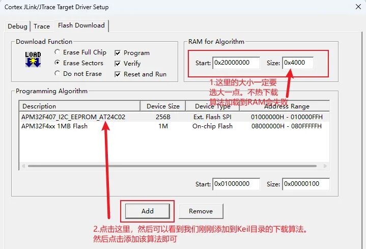
To program these storage devices with a single click using the download button in the Keil IDE, a corresponding download algorithm for the device is required. For Keil, the appropriate download algorithm xxx.FLM file is specified through the debug interface, and it can then be called, as shown in the figure below:
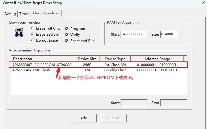
During the debugging download phase, Keil loads the algorithm file into the chip’s internal RAM, and the loaded RAM address and size can be configured in the screenshot above. The download algorithm file’s erase, program, and other functions can then be executed in RAM, allowing for operations such as downloading programs to storage devices or reading data during debugging.
The general process is illustrated in the figure below:
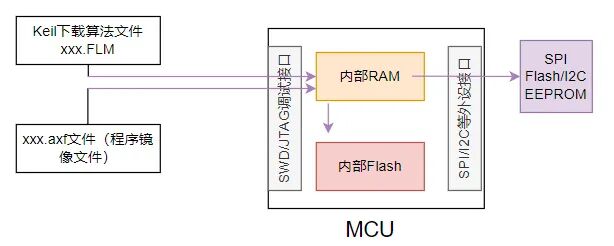
It mainly consists of two steps:
-
Load the download algorithm into RAM via the SWD/JTAG debug interface.
-
Execute the download algorithm’s erase, program, and other functions to program the internal Flash or perform programming operations on external SPI FLASH/I2C EEPROM via the MCU’s on-chip peripherals.
Additionally, as mentioned earlier, the download algorithm file is loaded into RAM for execution, and since we can set it to run at any RAM address, the code generated by the download algorithm must be position-independent to allow it to run at any RAM address.
2. Functions and Execution Flow of the Keil Download Algorithm
2.1 Functions Required for the Download Algorithm
According to the official documentation, to create a new download algorithm, the following functions must be implemented:
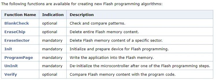
There are a total of seven functions, and the prototypes of these functions are already specified; we only need to implement the specific functionality based on different storage devices.
Among them, the functions marked as mandatory must be implemented for a new download algorithm, while the optional functions can be implemented or not based on need.
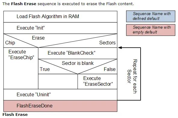
2.2 Erase Process
-
Load the algorithm into the chip’s RAM.
-
Execute the initialization function Init.
-
Perform the erase operation. The erase operation will choose to erase the entire chip or sector erase based on Keil’s configuration options.
-
Execute the Uninit function.
-
Erasure is complete.
2.3 Programming Process
The programming process involves downloading the compiled executable program to Flash or other storage devices.
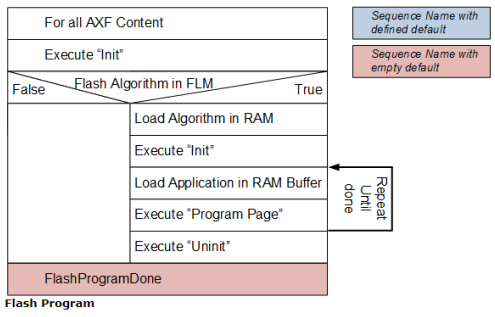
-
For all AXF file contents, execute the Init initialization function.
-
Check if the Flash algorithm is present in the FLM file. If not, the programming ends with a failure. If the programming algorithm exists, execute the following operations:
(1) Load the algorithm into RAM
(2) Execute the Init function
(3) Load the application program (data to be programmed) into the RAM Buffer
(4) Execute the Program Page programming function
(5) Execute the Uninit function
-
Programming is complete.
2.4 Verification Process
Verification involves comparing the data that needs to be downloaded to Flash from the AXF file with the actual data read from Flash.
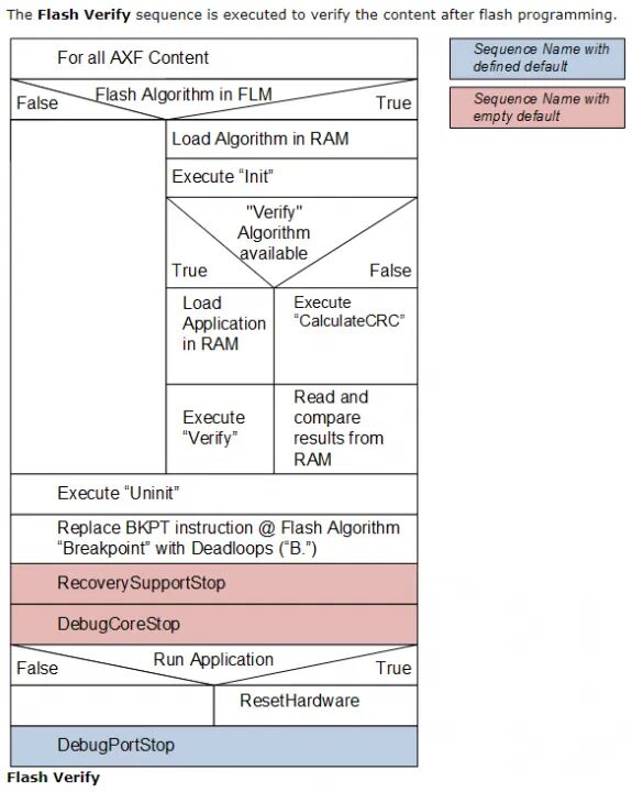
-
Check if the Flash algorithm is present in the FLM file. If not, the operation fails. If the programming algorithm exists, execute the following operations:
(1) Load the algorithm into RAM
(2) Execute the Init function
(3) Check if the FLM file contains a verification algorithm.
-
If it exists, load the application program into RAM and then execute the verification algorithm in the FLM file.
-
If it does not exist, calculate and compare the CRC values. Compare the CRC value calculated from the data read from Flash with the CRC value calculated from the data loaded into RAM from the axf file.
-
Execute the Uninit function.
After executing the Uninit function, the subsequent steps are not very clear; are these steps related to debugging and not relevant during code download?
3. Creating the I2C EEPROM Download Algorithm for the Keil Environment
Below, I will create a download algorithm for the AT24C02 EEPROM storage chip based on the APM32F407.
The official website has provided detailed steps for creating the download algorithm; the following steps are translated from the official website. Steps to create a new download algorithm:
-
Copy the contents of the ARM:CMSIS Pack folder (usually located at C:\Keil\ARM\Pack\ARM\CMSIS\ version \Device_Template_Flash) to a new folder.
-
Rename the project file NewDevice.uvprojx to reflect the new flash ROM device name, for example, MyDevice.uvprojx.
-
Open the project using uVision. From the toolbar, use the drop-down menu “Select Target” to define the processor architecture. Cortex-M is suitable for all Cortex-M0/M0+/M3 and M4 devices. This configuration assumes the use of a little-endian microcontroller. If using a big-endian microcontroller, select the correct processor core using Project – Options for Target – Device.
-
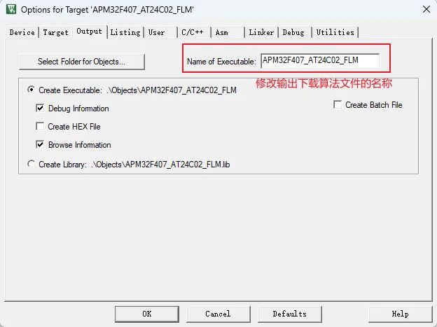
Open the dialog “Project – Target Options – Output” and change the content of the Executable File Name field to reflect the device, for example, MyDevice.
-
Adjust the programming algorithm in the FlashPrg file.
-
Adjust the device parameters in the FlashDev file.
-
Use Project – Build Target to generate the new Flash programming algorithm. The output file (e.g., MyDevice.FLM) must be added to the DFP.
The above steps are provided by the official website; now we will create a new download algorithm based on these steps.
3.1 Preparing the Download Algorithm Template
The template for the download algorithm is available when we install Keil. The official website states that it can be found in the Keil installation directory, but I could not find it in version 5.36; instead, I found it in C:\Users\YourUsername\AppData\Local\Arm\Packs\ARM\CMSIS\5.8.0\Device_Template_Flash.
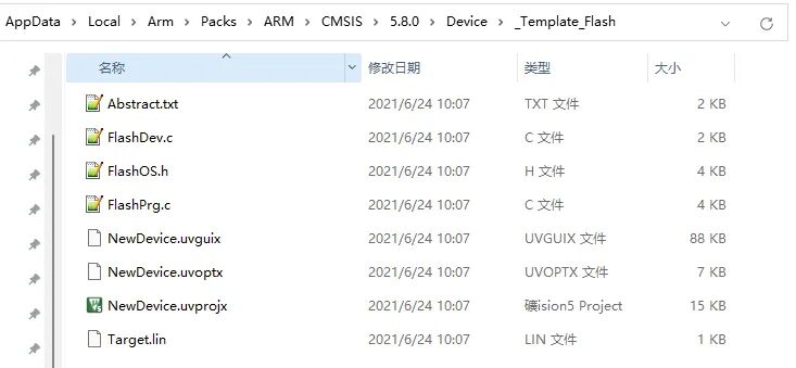
We will make a copy of this directory for backup and remember to remove the read-only attribute from this folder.
3.2 Keil Environment Setup
1. Modify the name of the copied template project based on the chip for which we are creating the download algorithm to enhance its recognizability.
2. Modify the selected target chip.
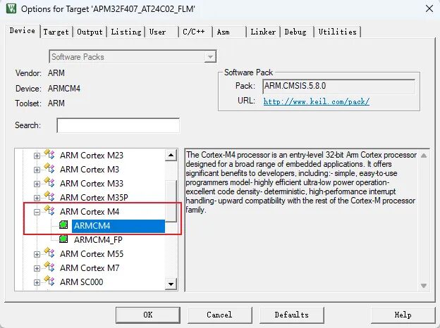
Since I am creating the download algorithm file based on the APM32F407, I will select the M4 core.
3. Modify the name of the generated download algorithm file.
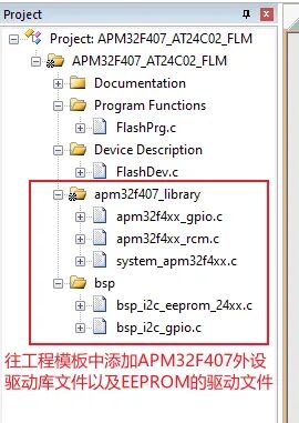
4. Add the APM32F407 peripheral driver library and the read/write driver files for the I2C EEPROM.
Since we are implementing the download algorithm for the I2C EEPROM, we must first ensure that the I2C EEPROM driver can read and write correctly. The I2C EEPROM driver can be verified from the examples we have implemented and then transferred for use.
3.3 Modifying the Programming Algorithm Functions in FlashPrg.c
This step is the most important; we mainly need to implement the various download algorithm functions in the FlashPrg.c file. According to the previous introduction, the functions that must be implemented for a new download algorithm are: Init/EraseSector/ProgramPage/Uninit. Other functions can be implemented based on need. Now let’s implement these functions one by one.
1. Implementation of the Init function
/*
* Initialize Flash Programming Functions
* Parameter: adr: Device Base Address
* clk: Clock Frequency (Hz)
* fnc: Function Code (1 – Erase, 2 – Program, 3 – Verify)
* Return Value: 0 – OK, 1 – Failed
*/
int Init (unsigned long adr, unsigned long clk, unsigned long fnc)
{
/* System initialization */
//SystemInit(); // If this function from the library is used, it will cause the download to fail at address 0x08000000, but actual tests show that it has been downloaded. The reason is unclear.
I2C_Init();
return 0;
}
In this function, we can initialize some operations for the programming storage, such as configuring the clock, initializing GPIO, etc.
2. Sector erase and chip erase functions
/*
* Erase complete Flash Memory
* Return Value: 0 – OK, 1 – Failed
*/
int EraseChip (void)
{
volatile int i = 0;
unsigned char tmepbuf[EE_PAGE_SIZE];
unsigned char adr = 0;
for(i = 0; i < EE_PAGE_SIZE; i++)
{
tmepbuf[i] = 0xFF;
}
for (i = 0; i < EE_SIZE / EE_PAGE_SIZE; i++)
{
ee_WriteBytes(tmepbuf, adr, EE_PAGE_SIZE);
adr += EE_PAGE_SIZE;
}
return 0;
}
/*
* Erase Sector in Flash Memory
* Parameter: adr: Sector Address
* Return Value: 0 – OK, 1 – Failed
*/
int EraseSector (unsigned long adr)
{
volatile int i = 0;
unsigned char tmepbuf[EE_PAGE_SIZE];
adr -= I2C_EEPROM_ADDR;
for(i = 0; i < EE_PAGE_SIZE; i++)
{
tmepbuf[i] = 0xFF;
}
ee_WriteBytes(tmepbuf, adr, EE_PAGE_SIZE);
return 0;
}
In fact, for EEPROM chips, data can be written without erasing. However, for demonstration purposes, we will implement these two erase functions. For EEPROM, erasing simply means writing 0xFF data to it.
3. Implementation of the ProgramPage function
#define I2C_EEPROM_ADDR 0x01000000
/*
* Program Page in Flash Memory
* Parameter: adr: Page Start Address
* sz: Page Size
* buf: Page Data
* Return Value: 0 – OK, 1 – Failed
*/
int ProgramPage (unsigned long adr, unsigned long sz, unsigned char *buf)
{
volatile int i = 0;
adr -= I2C_EEPROM_ADDR;
for(i = 0; i < sz/EE_PAGE_SIZE; i++)
{
ee_WriteBytes(buf+EE_PAGE_SIZE*i, adr+EE_PAGE_SIZE*i, EE_PAGE_SIZE);
}
if(sz%EE_PAGE_SIZE)
{
ee_WriteBytes(buf+EE_PAGE_SIZE*i, adr+EE_PAGE_SIZE*i, sz%EE_PAGE_SIZE);
}
return (0);
}
We can directly call the EEPROM driver write function. Additionally, the macro definition I2C_EEPROM_ADDR is used to define which area to store EEPROM data in our application code; the address can be defined arbitrarily, but it must not overlap with the MCU’s peripheral addresses, Flash, RAM, etc.
4. Implementation of the Uninit function
This function is generally called when exiting programming according to the previous Keil execution programming flow. We can perform recovery operations in this function. This function must be implemented; if no action is needed, we can leave this function empty.
/*
* De-Initialize Flash Programming Functions
* Parameter: fnc: Function Code (1 – Erase, 2 – Program, 3 – Verify)
* Return Value: 0 – OK, 1 – Failed
*/
int UnInit (unsigned long fnc) {
/* Add your Code */
return (0); // Finished without Errors
}
3.4 Modifying Device Parameters in FlashDev.c
In the FlashDev.c file, there is a structure constant named FlashDevice, which provides Keil with information about the programming device, such as the starting address for programming, total size, sector size, device type, etc. We can modify this information based on the type of device we are programming.
struct FlashDevice const FlashDevice = {
FLASH_DRV_VERS, // Driver Version, do not modify!
“APM32F407_I2C_EEPROM_AT24C02”, // Device Name
EXTSPI, // Device Type
0x01000000, // Device Start Address. EEPROM programming address.
0x00000100, // Device Size in Bytes
8, // Programming Page Size
0, // Reserved, must be 0
0xFF, // Initial Content of Erased Memory
6000, // Program Page Timeout 6000 mSec
6000, // Erase Sector Timeout 6000 mSec
// Specify Size and Address of Sectors
0x000008, 0x000000, // Sector Size 8B (32 Sectors)
// 0x010000, 0x010000, // Sector Size 64kB (2 Sectors)
// 0x002000, 0x030000, // Sector Size 8kB (8 Sectors)
SECTOR_END
};
3.5 Generating the Algorithm File
After implementing the programming algorithm functions in the FlashPrg.c file, we can directly compile to generate the xxx.FLM algorithm file.
Before compiling, we need to check that the generated code is position-independent code. The settings in Keil are as follows:

Both the C/C++ and Asm tabs should be checked to ensure the above configurations are selected.
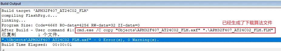
Click compile to generate the Keil download algorithm file.
4. Using and Testing the Newly Created Download Algorithm File
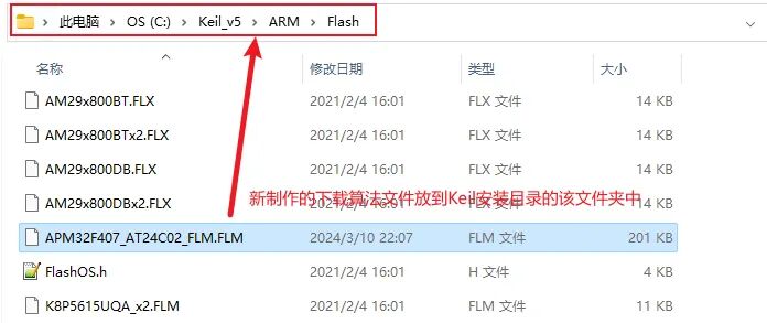
1. Place the generated download algorithm file in the Keil installation directory C:\Keil_v5\ARM\Flash for use.
2. Configure the download algorithm in the Keil environment.
3. Test and validate the APM32F407_I2C_EEPROM algorithm.
We use the download algorithm to download data to the EEPROM and then read it back through the application program to compare whether the written data is consistent, which allows us to determine if the EEPROM download algorithm is functioning correctly.
We will find an example for the APM32F407 EEPROM for testing.
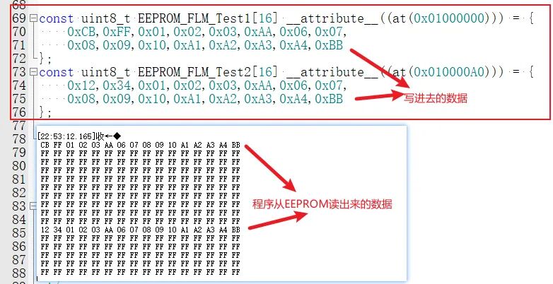
(1) First, define the data to be programmed into the EEPROM in the example:
const uint8_t EEPROM_FLM_Test1[16] __attribute__((at(0x01000000))) = {
0xCB,0xFF,0x01,0x02,0x03,0xAA,0x06,0x07,
0x08,0x09,0x10,0xA1,0xA2,0xA3,0xA4,0xBB
};
const uint8_t EEPROM_FLM_Test2[16] __attribute__((at(0x010000A0))) = {
0x12,0x34,0x01,0x02,0x03,0xAA,0x06,0x07,
0x08,0x09,0x10,0xA1,0xA2,0xA3,0xA4,0xBB
};
We specify that these arrays must be linked to the starting address 0x01000000 because the programming address for our EEPROM download algorithm is within this range. This address will be converted to the EEPROM programming address of 0 when used in the download algorithm; for example, the starting address of 0x01000000 corresponds to the EEPROM’s address 0.
(2) Then compile the download code to Flash and EEPROM.
During the download process, the address 0x01000000 needs to have data downloaded, and Keil will automatically call the EEPROM download algorithm to program the data into the EEPROM.
As shown, the download program completed without errors.
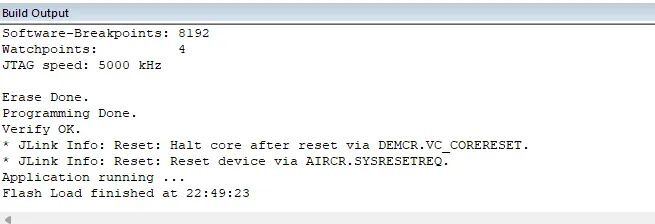
Then run the code to read the data from the EEPROM and compare whether it is consistent.
Note: The author of the article has provided example files in the original post; please visit the original 21ic forum to download if needed.
Original post link: https://bbs.21ic.com/icview-3364968-1-1.html
Or click below to read the original text to jump


↑↑↑ Click the card above to follow Jihai ↑↑↑