Click the blue text above to follow for continuous updates!!!
Introduction
Today, we will also not involve the Zigbee protocol, focusing solely on serial operations in the CC2530 microcontroller.
This article uses Serial Port 0 for data transmission. The main function is to send serial data from a PC’s serial debugging tool to the microcontroller, which receives and determines if the command is ON / OFF to decide the state of the LED light and respond to the serial debugging tool.
Through this article:
-
You will learn about the configuration of UART registers.
-
You will learn how to send data via the serial port.
-
You will know how to receive data via the serial port.
1. Principle Analysis
1. LED Function
As shown in the schematic diagram below, the LED will light up only when the P1.0 pin is at a low level, allowing the diode to conduct. 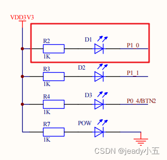
2. Serial Communication Function
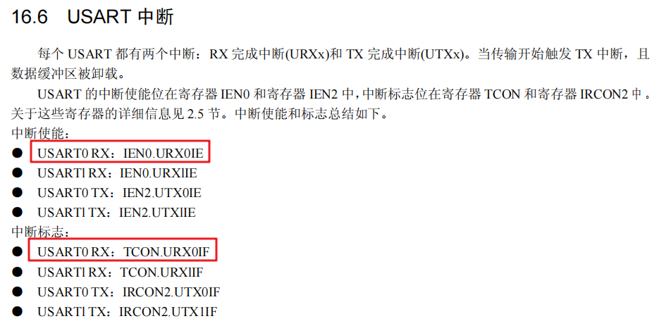
1) Enable Interrupts and Interrupt Flags
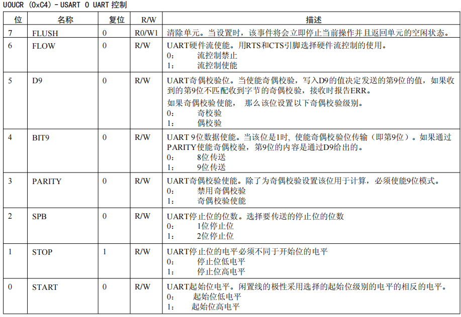
2) Stop Bits and Parity
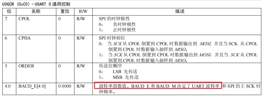
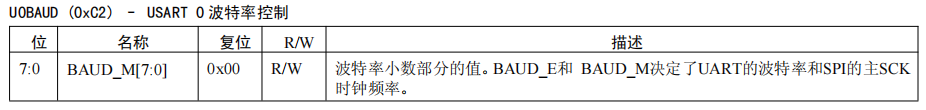
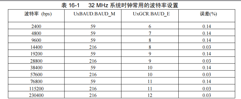
3) Baud Rate Settings
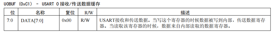
4) Sending and Receiving Serial Messages
2. Source Code
1. Function
Using the serial port to control the LED light’s on and off.
When the serial port receives ON, it turns on the LED and replies with OK; when it receives OFF, it turns off the LED and replies with OK; when it receives other commands, it does not operate on the LED and directly replies with ERROR.
2. Effect Diagram:
3. Source Code:
#include "iocc2530.h"
#include "string.h"

void initUART(){
  CLKCONCMD &= 0xbf;    // Set system clock source to 32MHZ crystal
  while(CLKCONSTA & 0x40); // Wait for crystal to stabilize
  CLKCONCMD &= 0xf8;    // Set system main clock frequency to 32MHZ

  PERCFG = 0x00;        // Position 1 P0 port
  P0SEL = 0x0c;         // Set P0_2, P0_3 for peripheral function, serial port

  U0CSR |= 0x80;        // Set to UART mode
  U0GCR |= 0x08;        // Baud rate settings
  U0BAUD = 59;          // Baud rate settings
  URX0IE = 1;           // Enable read interrupt
  EA = 1;               // Global enable

  U0CSR |= 0x40;        // Enable receiver
}

void send_uart(unsigned char *data,int len)
{
 int j;
 for(j=0;j<len;j++) "off\r\n")){="" "on\r\n")){="" #pragma="" &="0xfe;" )="" ){="" 0="" 0,="" 0;="" 20);="" 4);="" 6);="" ;="" __interrupt="" a="" as="" char="" code="" direction="" hello[20]="hello zigbee\r\n" i="" if(!strcmp(re,="" if(temp="\n" initled();="" initled(){="" inituart();="" int="" main(="" memset(re,="" normal="" o="" output="" p1.0="" p1_0="1;" p1dir="" p1sel="" re[20]="{" re[strlen(re)]="temp;" return="" send_uart("error\r\n",="" send_uart("ok\r\n",="" send_uart(dat,sizeof(dat));="" set="" temp="U0DBUF;" u0dbuf="*data++;" uart_isr(void){="" unsigned="" urx0if="0;" utx0if="0;" vector="URX0_VECTOR" void="" while(1){}="" while(utx0if="0);" {="" |="0x01;" }="" };="" }<="" }else="" }else{=""></len;j++)>
If this is useful, please give it a thumbs up and share!