With the continuous development of Internet of Things technology, smart home systems are no longer a fantasy, and more and more smart home products are occupying market share. Smart homes apply electronic technology, wireless communication technology, etc., allowing household appliances and security devices in the living environment to be remotely controlled via wireless networks. This enhances people’s comfort and security, thereby improving their quality of life.
1 Overall System Design Concept
This article constructs a star-shaped Zigbee data transmission module network centered on Zigbee technology and the Android system. The system uses Android smartphones as the operating terminal and WIFI as the data transmission method, utilizing Zigbee modules for terminal control. Users can access the embedded server (computer) at home through the control interface software installed on the Android phone via WIFI. The server then sends commands to the connected host node through the USB port, and finally, the host node controls various terminal nodes through the Zigbee module, allowing users to quickly and conveniently cut off (or turn on) power, monitor for intruders, etc., achieving true intelligent control.
The overall system design block diagram is shown in Figure 1.
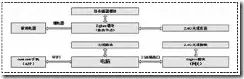
Figure 1 Overall System Design Block Diagram
2 System Hardware Implementation
The system consists mainly of four parts: Zigbee wireless module (gateway), Zigbee wireless module (node), computer, and Android smartphone terminal. It can use a regular Android phone with an application program to remotely control the on/off state of household appliances through the home LAN, and perform real-time Zigbee data collection of indoor temperature, humidity, light intensity, smoke concentration, and personnel flow, displaying this information on the phone. The main hardware design of this system is the Zigbee data transmission module circuit, with the Zigbee chip selected being the CC2530F256 produced by TI Company, which is a dedicated Zigbee chip based on 2.4GHZ wireless transmission and reception, integrated with an 8051 core. The chip is powered by a 3.3V power supply, and the Zigbee data transmission module is equipped with interfaces for a smoke sensor (for detecting excessive smoke, which may indicate gas leakage or fire), relay interface (to control household appliance power), temperature sensor interface (to collect temperature values), human infrared interface (to monitor personnel movement), and light-sensitive sensor interface (to detect light intensity), used for Zigbee data collection of the above information, and sending the collected data to the Zigbee wireless module gateway via the Zstack protocol stack and 2.4GHZ wireless transmission. After obtaining the values from the node devices, the Zigbee wireless module gateway transmits the data to the computer via a serial-to-USB interface for display. The block diagram of the Zigbee module is shown in Figure 2.
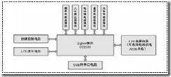
Figure 2 Zigbee Module Block Diagram
3 System Software Implementation
The system software mainly includes three parts: Zigbee gateway module, Zigbee module, and Android terminal APP software design. The flowchart of the gateway module is shown in Figure 3, and the flowchart of the node module is shown in Figure 4.
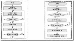
Figure 3 Node Module Flowchart Figure 4 Gateway Module Flowchart
The Android terminal APP software should include functions such as setting and changing the server IP address, sending control commands with one click, allowing access for multiple nodes, and displaying information collected from each node. The interface design is divided into the main interface and various functional interfaces. First, click to enter the main interface, input the IP address of the server, establish a connection with the computer through the WIFI network, and then send control commands through the control buttons while displaying received information such as temperature and light intensity. The mobile operation interface is shown in Figure 5.
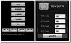
Figure 5 Mobile Operation Interface
4 Debugging Simulation and Conclusion
Following a step-by-step approach, each module and functional node of the system was tested. After testing, the functions achieved by the system include: (1) Realizing wireless communication between the Zigbee gateway module and the Zigbee module. (2) The Zigbee wireless module node can complete functions such as smoke detection, temperature detection, human infrared detection, light intensity Zigbee data collection, and relay control. (3) Control of nodes can be performed through application software installed on the computer as well as through the Android phone APP application software. After testing, the system can conveniently monitor the sensor signals connected to each functional module, the system operates stably and reliably, and the data displayed is accurate. It has truly achieved intelligent home control.