Introduction
Today’s content does not involve the Zigbee protocol, but rather the use of the CC2530 microcontroller to control an LED with a button.
This tutorial is divided into two parts:
-
Polling to detect button levels for controlling the LED.
-
Using button interrupts to control the LED.
1. Principle Analysis
1. Button Functionality
The schematic diagram is shown below. As can be seen, the button is at a high level when not pressed and at a low level when pressed. The button used in today’s code is associated with pin P0.1, referred to as BTN1.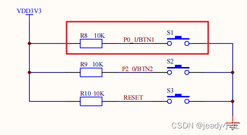
2. LED Functionality
As shown in the schematic diagram below, the LED will light up when pin P1.0 is at a high level, allowing the diode to conduct.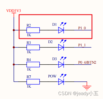
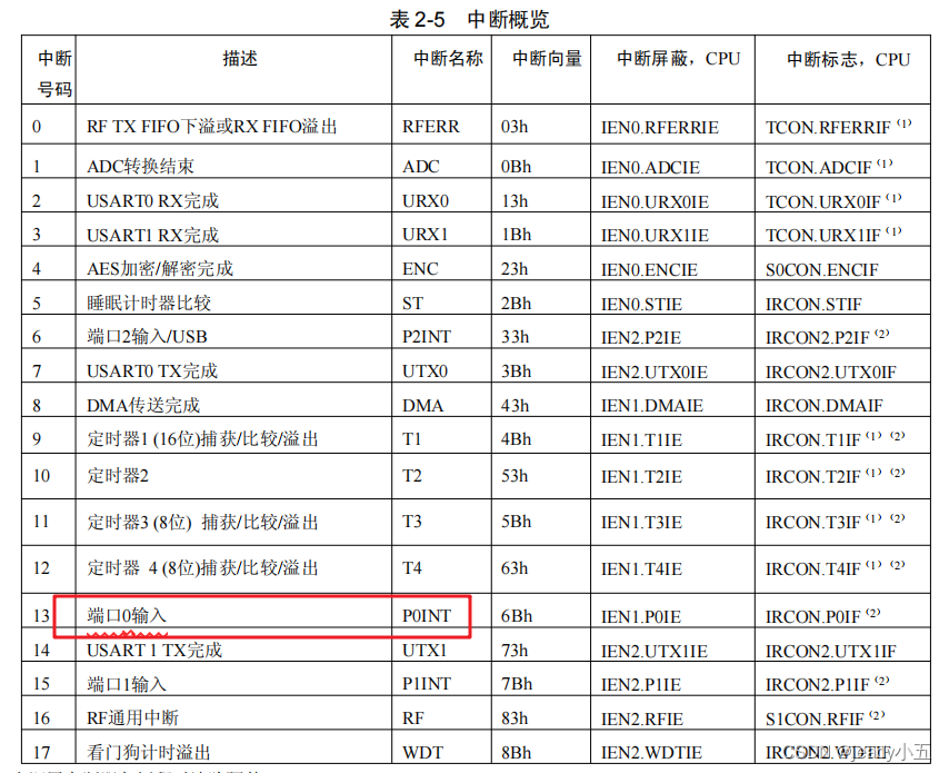
3. Interrupt Functionality
According to the CC2530 data sheet, the general steps to implement interrupts are as follows: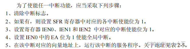
2. Source Code
1. Polling Button to Control LED
1) Functionality
The LED lights up when the button is pressed and turns off when released.
2) Effect Diagram:
3) Source Code:
#include "iocc2530.h" // Import CC2530 header file

void initLed();
void initKey();
void sleep(int); // ms delay function

int main( void )
{
  initLed();    // Initialize LED pin
  initKey();    // Initialize button pin
  while(1){         // Loop to check P0.1 I/O button input value
    if(!P0_1){      // Button pressed
      sleep(20);    // Debounce
      if(!P0_1){    // Button still pressed
        P1_0 = 0;   // Turn on LED
      }
    }else{
        P1_0 = 1;       // Turn off LED
    }
  }
  return 0;
}

void initKey(){
  P0SEL &= 0xfd;    // Set P0.1 as normal I/O
  P0DIR &= 0xfd;    // Set P0.1 as input direction
  P0INP &= 0xfd;    // Set P0.1 input mode to pull-up/pull-down
}

void initLed(){
  P1SEL &= 0xfe;    // Set P1.0 as normal I/O
  P1DIR |= 0x01;    // Set P1.0 as output direction
}

void sleep(int delay){ // A rough delay effect
  for(int i = 0; i < delay; i++){
    for(int j = 0; j < delay; j++);
  }
}
2. Button Interrupt to Control LED
1) Functionality
Pressing the button once turns on the LED, pressing it again turns it off.
2) Effect Diagram:
3) Source Code:
#include "iocc2530.h" // Import CC2530 header file

void initLed();
void initKey();
void sleep(int);
void initInter();   // Initialize button interrupt

int main( void )
{
  initLed();    // Initialize LED port
  initKey();    // Initialize button port
  initInter();  // Initialize interrupt
  while(1){     // Stay in place, waiting for button interrupt
//    P1_0 = !P1_0;
//    sleep(1000);
  }
}

#pragma vector = P0INT_VECTOR // Place interrupt function at P0INT address
__interrupt void P0_ISR(void){  // Function executed during P0 port interrupt
  if(P0IFG & 0x02){ // P0.1 button interrupt
    sleep(2);       // Debounce
    if(!P0_1){      // Button still pressed
      P1_0 = !P1_0; // Toggle LED P1.0
    }
  }
  P0IFG &= 0xfd;    // Clear P0.1 interrupt flag
  P0IF = 0;         // Clear P0 port interrupt
}

void initInter(){
  P0IFG = 0;            // Step 1. Clear all interrupt flags for P0 port
  P0IEN |= 0x02;        // Step 2. Enable P0.1 pin interrupt
  IEN1 |= 0x20;         // Step 3. Enable port 0 interrupt
  EA = 1;               // Step 4. Enable global interrupt
  PICTL |= 0x01;        // Optional. Set P0 port to trigger interrupt on falling edge
}

void initKey(){
  P0SEL &= 0xfd;    // Set P0.1 as normal I/O
  P0DIR &= 0xfd;    // Set P0.1 as input direction
  P0INP &= 0xfd;    // Set P0.1 input mode to pull-up/pull-down
}

void initLed(){
  P1SEL &= 0xfe;    // Set P1.0 as normal I/O
  P1DIR |= 0x01;    // Set P1.0 as output direction
}

void sleep(int ms){ // ms delay effect
  for(int i = 0; i < ms * 1000; i++){
    for(int j = 0; j < 32; j++);
  }
}
3. Conclusion
You can contact me through the public account to join the group for communication and learning, and to improve together.