Wireless network technology is essentially a competition among power consumption, distance, rate, and networking methods. Is it possible to achieve low power consumption, long distance, and quick networking and deployment?
The standard Zigbee network protocol includes coordinators, routers, and terminal nodes. To establish a Zigbee network, in addition to the necessary coordinator, only routers or terminal nodes need to be added.
However, different application scenarios require different types of networking structures: point-to-point, star, relay routing, hybrid, etc. Therefore, quick, efficient, stable, convenient, and flexible are higher demands placed on networking protocols.
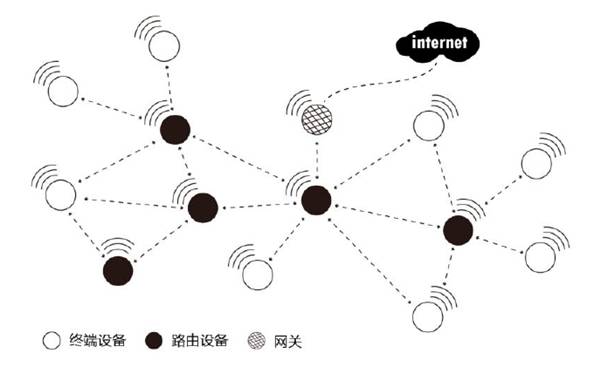
Figure 1 Zigbee Network Topology
1. Fastzigbee Protocol
Changing the perspective, if any node on the network has peer-to-peer data transmission capabilities and does not require a coordinator to manage the network, then any node in the network can actively transmit data. This means users do not have to worry about the specific network structure, which is obviously more convenient to use.
Based on this, ZLG has developed the Fastzigbee transparent peer-to-peer network protocol based on years of practical experience and the Zigbee protocol stack. Its features are as follows:
-
Zero delay startup, no need to wait for network joining;
-
Large node capacity, theoretically up to 65,535 nodes;
-
Three-wire serial port fully transparent transmission mode, customizable data format;
-
No secondary development needed, can quickly implement dynamic configuration and self-organizing network functions;
-
Quickly add routing, smart routing algorithms that are ready to use, quickly restore communication, and facilitate construction.
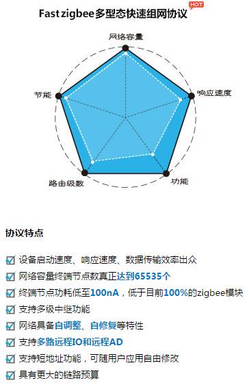
Figure 2 Features of Fastzigbee Protocol
2. Self-Organizing Network Implementation
The Fastzigbee protocol has provided a solid foundation for networking, but can it also provide better support for deployment and construction?
Of course, ZLG has added self-organizing network functionality within the Fastzigbee protocol to simplify the complex development process of wireless products. Below, using the AW516x series transparent transmission module as an example, we provide engineers with two implementation methods.
In self-organizing network mode, the host module automatically selects an unused PAN ID and channel number from the surrounding area to form an independent network and can automatically assign a unique local network address to the slave module in an incremental manner. When using the slave module, after enabling the self-organizing network function, no configuration operation is required. Once the slave module joins the network, it can communicate with the host.
2.1 Hardware I/O Control
(1) The host module has two workflows controlled by the JOIN pin (IO1) and the DETECT pin (IO2).
-
When the JOIN pin is low, the host module operates in networking mode, allowing the slave module to join the network. When the JOIN pin goes high, the host module enters normal operation, and the slave module can no longer join the network.
-
When the module detects a low level on the DETECT pin for more than 3 seconds, the host module enters the mode to reacquire network parameters. At this point, the host module will randomly generate a new PAN ID (0x0000~0xFFFF) and channel number (11~26), and check if the newly generated PAN ID and channel number are already in use by other networks. If they are in use, it will regenerate. After regenerating the PAN ID and channel number, all slaves under this host need to perform the network joining operation.
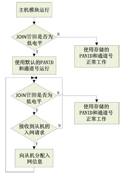
Figure 3 Host Module Networking Workflow
(2) The slave module has two operating modes: network joining request and network leaving request, determined by the state of the JOIN pin.
-
When the JOIN pin is low and the duration is less than 3 seconds (short low), the slave module operates in network joining request state;
-
When the JOIN pin is low and the duration is more than 3 seconds (long low), the slave module operates in network leaving request state; if the JOIN pin is high, the slave module enters normal operating state using the stored PAN ID and channel number.
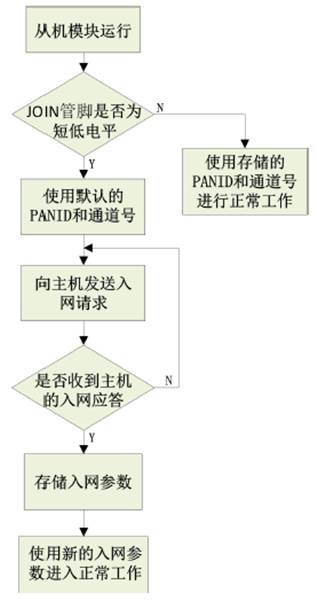
Figure 4 Slave Module Joining Process
2.2 Software Command Configuration
The host module can allow the slave to join the network using the IO port control or by using commands to enable the host to allow the slave to join the network.
Table 1 Command to Allow Slave to Join Network
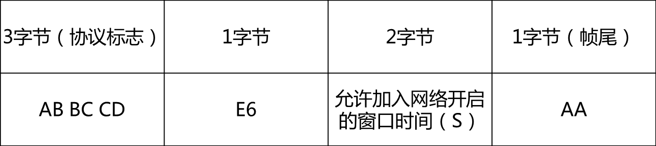
The window time for allowing joining the network starts when the command to allow joining is sent to the host, and the host begins to accept joining requests from slaves. Once this window time is reached, the host no longer accepts joining requests. After the window time ends, the host enters normal operation.
In addition, commands can also query the stored slave information, query the master-slave status, etc.
3. Test Example
All operations are based on ZLG’s Zigbee evaluation board: AW516x Demo Board.
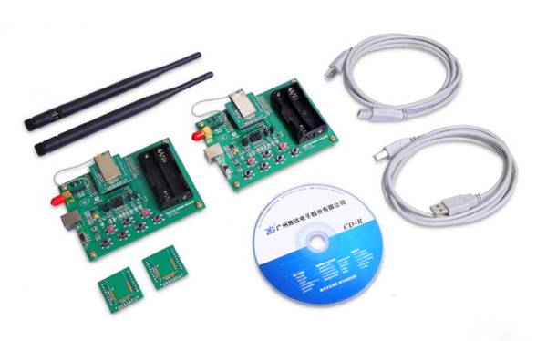
Figure 5 Zigbee Evaluation Kit
Steps:
(1) Use evaluation board 1 as the host module and evaluation board 2 as the slave module;
(2) Pull the JOIN pin (IO2) of evaluation board 1 to low, putting the host in a state to allow slaves to join;
(3) Briefly pull the JOIN pin (IO2) of evaluation board 2 to low for less than 3 seconds, putting the slave module in network joining request state. If there are multiple slave boards, you can sequentially connect IO2 to perform the joining operation;
(4) After joining is complete, the slave returns to normal high state, and the JOIN pin (IO2) of evaluation board 1 is pulled back to high, and the host module enters normal workflow.
Communication Test:
Connect to PC, open two serial debugging assistants, and perform transparent data transmission.
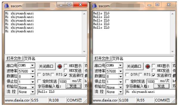
Figure 6 Communication Test
Reply with the keyword 【Wireless Communication】 to see more related technical topics.
Public Account Introduction