
Gift to Readers

Conducting research involves a profound system of thought, requiring researchers to be logical, meticulous, and earnest. However, effort alone is not enough; often leveraging resources is more important than sheer hard work. Additionally, one must have innovative ideas and inspirations that look up to the stars. It is recommended that readers browse in order to avoid suddenly falling into a dark maze without finding their way back. This article may not reveal all the answers to your questions, but if it can clarify the clouds of doubt rising in your mind, it may create a beautiful sunset of colors. If it brings you a storm in your spiritual world, then take the opportunity to brush off the dust that has settled on your ‘lying flat’ state.
Perhaps, after the rain, the sky will be clearer…


01

Overview


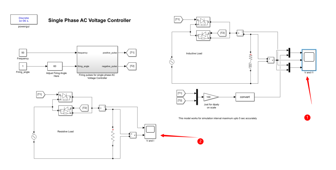
Simulation of a Single-Phase AC Voltage Controller with Two Back-to-Back Thyristors
This model simulates a single-phase AC voltage controller. The firing angle can be adjusted from zero degrees to 180 degrees. The power supply voltage and frequency can be adjusted from the model properties.
1. Introduction
The single-phase AC voltage controller controls the effective value of the output voltage by adjusting the conduction angle of the thyristors. This article will use two back-to-back connected thyristors to simulate the single-phase AC voltage controller and discuss its working principle and characteristics.
2. Circuit Model
1. Circuit Structure
The circuit consists of two back-to-back connected thyristors (VT1 and VT2), an AC power supply, a load resistor R, and a triggering circuit. Thyristors VT1 and VT2 are responsible for conducting during the positive and negative half-cycles of the AC power supply, respectively.
2. Working Principle
When the power supply voltage is in the positive half-cycle, the triggering circuit triggers VT1, causing it to conduct, while VT2 remains off due to the reverse voltage. In the negative half-cycle of the power supply voltage, the triggering circuit triggers VT2, causing it to conduct, while VT1 turns off due to the reverse voltage. By adjusting the firing angle (the angle between the moment the thyristor starts conducting and the zero crossing of the power supply voltage), the effective value of the output voltage can be controlled.
3. Model Parameter Settings
1. Power Supply Voltage and Frequency
The power supply voltage and frequency can be adjusted from the model properties. For example, the power supply voltage can be set to 220V, and the frequency to 50Hz.
2. Firing Angle
The firing angle is a key parameter of the model, adjustable from 0° to 180°. The adjustment of the firing angle is achieved through the triggering circuit, which generates corresponding triggering pulses for each half-cycle of the power supply voltage based on the preset firing angle.
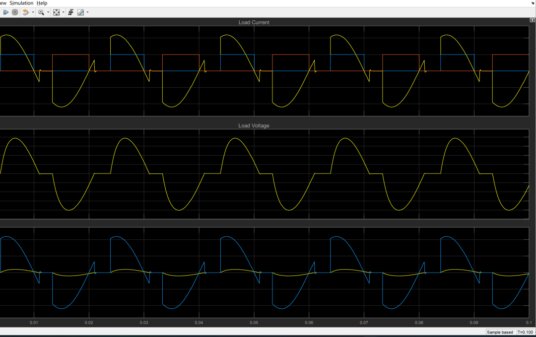
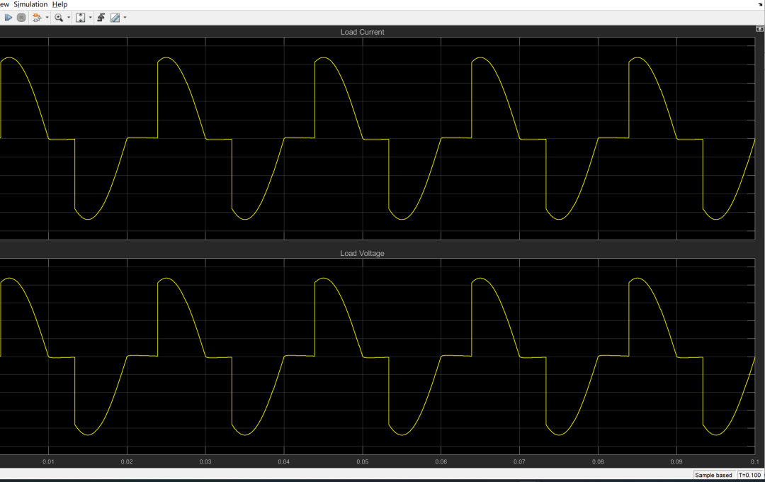
4. Simulation Experiment
1. Experiment Objective
Through simulation experiments, observe the waveform and effective value changes of the output voltage at different firing angles to verify the model’s effectiveness.
2. Experiment Steps
(1) Set the power supply voltage and frequency. (2) Adjust the firing angle to 0°, 30°, 60°, 90°, 120°, 150°, and 180°. (3) Record the output voltage waveform and effective value at each firing angle.
3. Experiment Results and Analysis
(1) When the firing angle is 0°, the thyristor conducts throughout the entire power supply voltage cycle, and the output voltage equals the power supply voltage. (2) As the firing angle increases, the effective value of the output voltage gradually decreases. This is because the conduction time of the thyristor in each half-cycle becomes shorter, leading to a lower average output voltage. (3) When the firing angle is 180°, the thyristor does not conduct throughout the entire power supply voltage cycle, and the output voltage is zero.
5. Conclusion
Through simulation experiments, the effectiveness of the single-phase AC voltage controller with two back-to-back connected thyristors has been verified. This model can flexibly adjust the effective value of the output voltage based on the preset firing angle, making it suitable for various applications requiring precise voltage control.


02
Running Results
03
Partial Code
04
References
Some content in this article is sourced from the internet, and references will be noted. If there are any inaccuracies, please feel free to contact us for removal.
[1] Liu Wenhua, Song Qiang, Zhang Dongjiang, et al. “50MVA STATCOM Chain and Its Back-to-Back Rated Condition Operation Test” [J]. Journal of Electrical Engineering, 2005, 20(2):6.
[2] Wang Yingjie, Li Bin, Tian Fang. “Electrical Design of the High Ridge Back-to-Back Project Converter” [J]. Electrical Engineering Digest, 2012.
[3] Cai Chao. “Research on High-Speed Railway Hybrid Reactive Power Compensation System Based on Immune Multi-Agent” [D]. Wuhan University, 2013.


05
Simulink Simulation Download