Hello everyone, good evening~
Today is still a technical article!

Siemens Modbus RTU Communication:
S7-200 smart Modbus RTU Master Communication (√)
S7-200 smart Modbus RTU Slave Communication (√)
RS485/232 Communication Ports and DP Connector Connection Methods
S7-1200 Modbus (RTU) Instruction V3 Basic Functions
S7-1200 Modbus (RTU) Instruction V4 New Functions

Each S7-200 SMART CPU provides an Ethernet port and an RS485 port (Port 0). The standard CPU additionally supports the SBCM01 signal board (Port 1), which can be configured via the STEP7-Micro/WIN SMART software as an RS232 or RS485 communication port.
 CPU Port Pin Assignment
1. The integrated RS485 communication port (Port 0) of the S7-200 SMART CPU is a 9-pin D-type connector compatible with RS485. The pin assignment of the integrated RS485 communication port of the CPU is shown in Table 1: Pin Assignment Table for Integrated RS485 Port of S7-200 SMART CPU.
Table 1: Pin Assignment Table for Integrated RS485 Port of S7-200 SMART CPU
Table 1
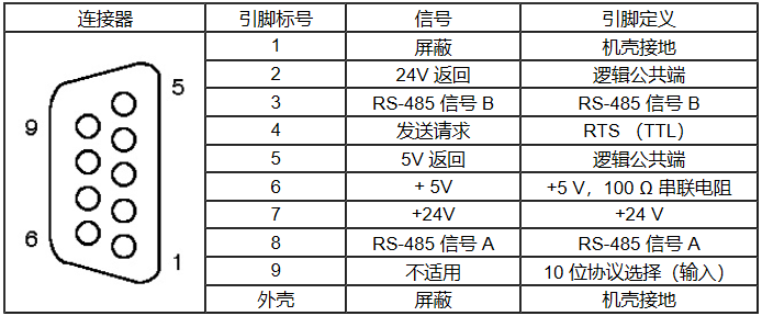
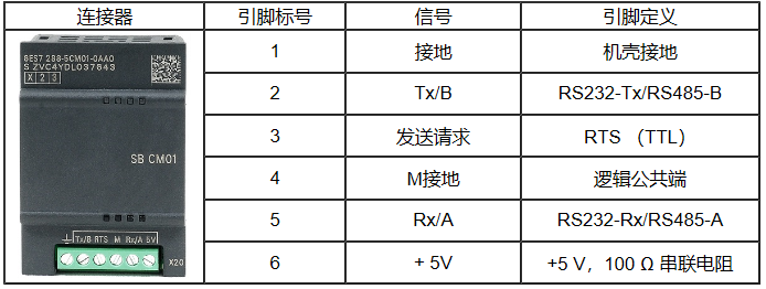
2. The standard CPU additionally supports the SBCM01 signal board, which can be configured as an RS485 or RS232 communication port via the STEP7-Micro/WIN SMART software. Table 2 provides the pin assignment for the SBCM01 signal board.
Table 2: Pin Assignment Table for SBCM01 Signal Board Port (Port 1)
Table 2
The process of configuring the SBCM01 signal board as an RS485 or RS232 communication port using the STEP7-Micro/WIN SMART software is shown in Figure 1-1: SBCM01 Signal Board Configuration Process.
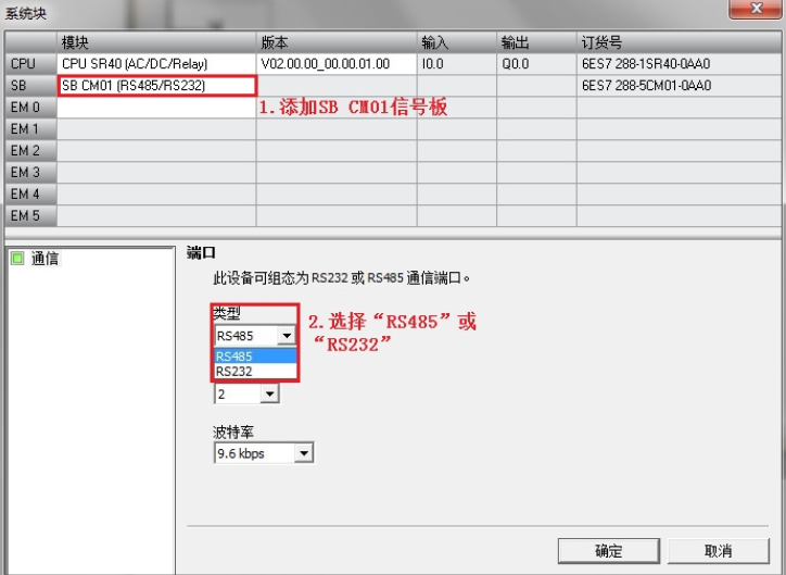 Figure 1-1EMDP01 Communication Port Pin Assignment
The RS485 serial communication interface on the EMDP01 is a 9-pin mini D-type socket compatible with RS485, compliant with the PROFIBUS standard specified by the European standard EN50170. The following figure introduces the pin assignment of the communication port.
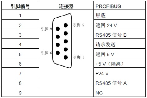 Figure 1-2Pin Assignment for S7-200 SMART EMDP01 Communication Port
Ethernet Port Connection
The Ethernet port of the S7-200 SMART CPU has two network connection methods: direct connection and network connection.
Direct Connection:
When a S7-200 SMART CPU communicates with a programming device, HMI, or another S7-200 SMART CPU, it is a direct connection. Direct connection does not require a switch; just connect the two devices directly with a network cable, as shown in Figure 1-3: Direct Connection of Communication Devices.
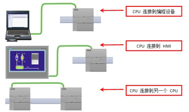 Figure 1-3 Direct Connection of Communication Devices
Network Connection:
When two or more communication devices communicate, a switch is required for network connection. The Siemens CSM12774 port switch can be used to connect multiple CPUs and HMI devices, as shown in Figure 1-4: Network Connection of Multiple Communication Devices.
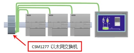
Figure 1-4 Network Connection of Multiple Communication Devices
RS232 Connection:
The RS232 network is a point-to-point connection between two devices, with a maximum communication distance of 15m and a maximum communication rate of 115.2Kbit/s. RS232 connections can be used to connect scanners, printers, modems, and other devices. The SBCM01 signal board can be configured as an RS232 communication port, and a typical RS232 wiring method is shown in Figure 1-5: RS232 Connection Diagram of SBCM01 Signal Board.
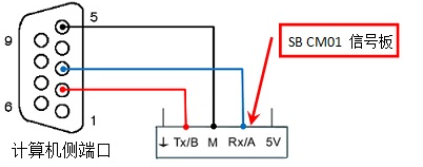 Figure 1-5 RS232 Connection of SBCM01 Signal Board
RS485 Network Connection:
RS485 network transmission distance and baud rate:
RS485 network is a linear bus network using shielded twisted pair cable, with termination resistors required at both ends of the bus. RS485 networks allow a maximum of 32 communication nodes per segment, and the maximum cable length is determined by whether the communication port is isolated and the baud rate, as shown in Table 3: Maximum Cable Length for RS485 Segments.
Table 3
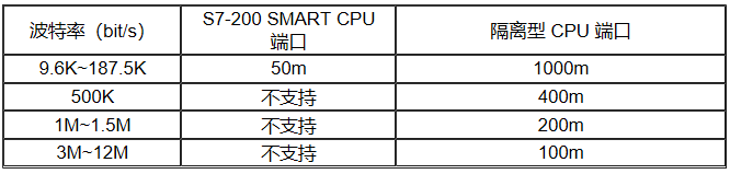
The integrated RS485 port of the S7-200 SMART CPU and the SBCM01 signal board are both non-isolated communication ports, allowing a maximum communication distance of 50m. This distance is from the first communication node in the segment to the last node. If the number of communication nodes exceeds 32 or the communication distance exceeds 50m, an RS485 repeater is needed to extend the network connection.
Note
The integrated RS485 port of the S7-200 SMART CPU and the SBCM01 signal board are both non-isolated. When communicating with other nodes in the segment, it is necessary to ensure equipotential connection of reference point potentials, or use RS485 repeaters to provide isolation for the network. Different reference point potentials may cause communication errors or port damage during communication between nodes.
When connecting the S7-200 SMART CPU to other nodes, the M terminal of the sensor power supply at the bottom right corner of the CPU module can be connected to the 0V reference point of the communication port of other nodes to achieve equipotential connection.
Today, Xiao Zhi shared “Siemens PLC Communication – Modbus RTU Communication and Connection Methods.” You can save it for use. If you encounter any problems or misunderstandings, you can add Xiao Zhi V:18018269808 for private chat or leave comments. If you like, please follow Xiao Zhi, like, and share, thank you!
Recently, staying at home, we have also launched many activities, with discounts on learning course packages! Helping everyone learn!



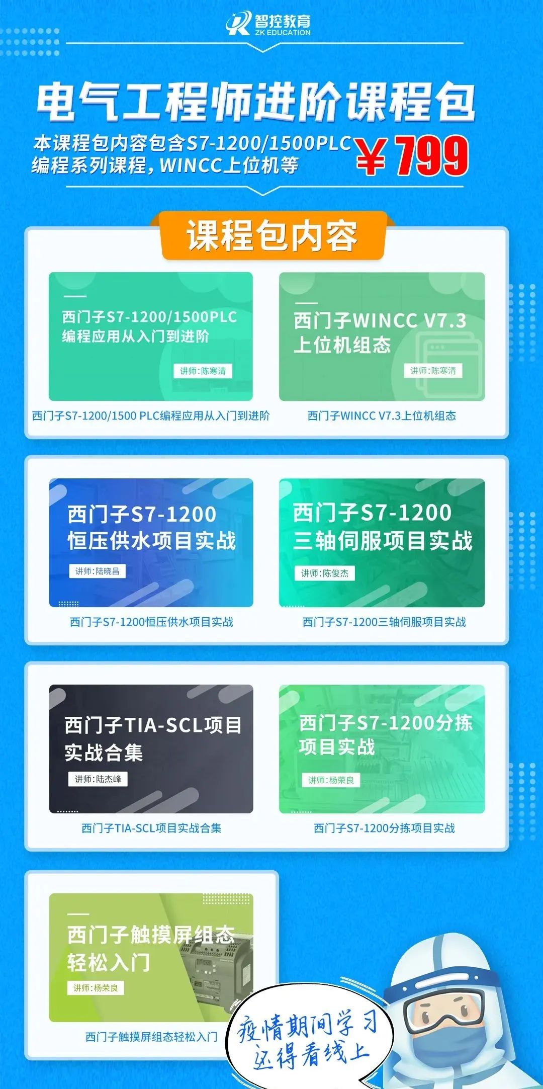


Smart Control Education Official Website:http://plc.czzkplc.com/czplc/home Free materials and courses can be found on the website!
You can purchase via the mini program!

● Siemens PLC Communication – Modbus RTU Communication – S7-200 smart Modbus RTU Slave Communication
● Siemens PLC Communication – 200 smart and 1200 PLC S7 Communication
● Common Instructions in Boto: EIXT Immediate Exit Loop
● Common Instructions in Boto: How to Use WHILE..DO Loop Instruction?
● Common Instructions: FOR TO DO Explicit Loop Count Tutorial
● Super Practical!! Creating Multiple Branches with CASE…OF Instruction in Boto
● If…THEN Conditional Execution Instruction in Boto that You Can Learn Just by Reading Carefully