LoRa Study: Setting and Explanation of Key LoRa Parameters (Spreading Factor, Coding Rate, Bandwidth)
-
1. Spreading Factor (SF)
-
2. Coding Rate (CR)
-
3. Signal Bandwidth (BW)
-
4. Relationship between LoRa Signal Bandwidth BW, Symbol Rate Rs, and Data Rate DR
-
5. Setting of LoRa Signal Bandwidth, Spreading Factor, and Coding Rate
For specific applications, developers can optimize LoRa modulation and demodulation technology through the three key design parameters: modulation spreading factor, modulation bandwidth, and error correction coding rate.
1. Spreading Factor (SF)
LoRa uses multiple information chips to represent each bit of payload information. The speed of sending spread information is called the symbol rate (Rs), and the ratio of chip rate to the nominal Rs is the spreading factor (SF), which indicates the number of symbols sent for each information bit. LoRa’s spreading factor range: 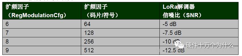
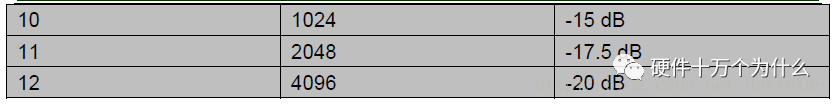
Note: Because different SFs are orthogonal to each other, the SF of both the sending and receiving ends must be known in advance. Additionally, the signal-to-noise ratio at the receiver’s input must also be known. Under negative signal-to-noise ratio conditions, signals can still be received normally, which improves the sensitivity of the LoRa receiver, link budget, and coverage.
Understanding the Concept of Spreading Factor:
In simple terms, when spreading, each bit of your data is multiplied by the spreading factor. For example, if there is a 1 bit to be transmitted, when the spreading factor is 1, the data 1 is represented by one 1. When the spreading factor is 6, it is represented as 111111, meaning that each bit is represented by a 6-bit data. This increases the total amount of data to be transmitted by 6 times. After spreading, transmission can reduce the bit error rate, which is the signal-to-noise ratio, but under the same data amount, it reduces the actual data that can be transmitted. Therefore, the larger the spreading factor, the smaller the data transmission rate (bit rate).
Using the LoRa Spreading Factor:
When the spreading factor SF is 6, the data transmission rate of LoRa is the fastest, so this spreading factor is only used in specific situations. When using it, the LoRa chip SX127x needs to be configured:
-
In RegModemConfig2, set the Spreading Factor to 6
-
Set the header to implicit mode
-
Write 0b101 into bits 2 to 0 of register address (0x31)
-
Write 0x0C into register address (0x37)
2. Coding Rate (CR)
The coding rate is the proportion of useful parts in the data stream. The coding rate (or information rate) is the proportion of useful parts (non-redundant) in the data stream. In other words, if the coding rate is k/n, then for every k bits of useful information, the encoder generates a total of n bits of data, where n-k is redundant. LoRa uses cyclic error correction coding for forward error detection and correction. Using this method results in transmission overhead. The data overhead generated during each transmission is as follows: 
In the presence of interference, forward error correction can effectively improve the reliability of the link. Thus, the coding rate (anti-interference performance) can change with the channel conditions, and the coding rate can be included in the header for the receiver to parse.
3. Signal Bandwidth (BW)
Increasing the BW can improve the effective data rate to shorten transmission time, but at the cost of sacrificing some receiver sensitivity. For the LoRa chip SX127x, the LoRa bandwidth is double-sided bandwidth (full channel bandwidth), while the BW for FSK modulation refers to single-sided bandwidth.
LoRa bandwidth options:
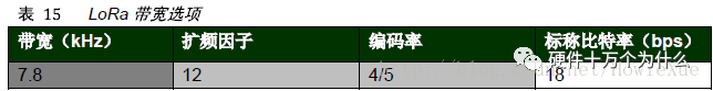
Note: The lower frequency band (169MHz) does not support 250K and 500KHz BW.
4. Relationship between LoRa Signal Bandwidth BW, Symbol Rate Rs, and Data Rate DR
The LoRa Symbol Rate Rs can be calculated using the following formula:
Rs=BW/(2^SF)
Sending one chip per Hz per second.
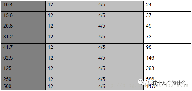
The LoRa Data Rate DR can be calculated using the following formula:
DR= SF*( BW/2^SF)*CR
5. Setting of LoRa Signal Bandwidth, Spreading Factor, and Coding Rate
LoRaWAN mainly uses a 125kHz signal bandwidth setting, but other dedicated protocols can utilize other signal bandwidth (BW) settings. Changing BW, SF, and CR also changes the link budget and transmission time, requiring a trade-off between battery life and distance.