
Summary: Recently, it has been snowing in many places, including Hunan, Hubei, and Xi’an. Students who raise tropical plants and pets need to pay more attention to the indoor temperature. Below is a practical and easy-to-make thermometer. It is built using the DS18B20 temperature sensor and OLED module, with the development board being Arduino.

The source code and 3D files for this project can be obtained by replying: 20211228.
1. Materials List
-
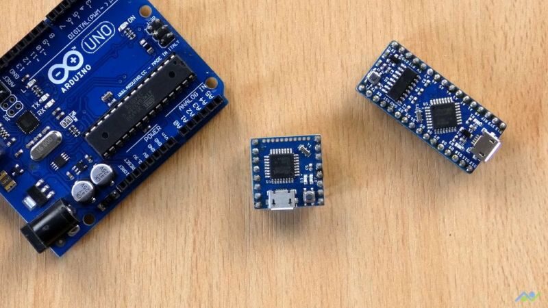
Arduino × 1 -
DS18B20 Temperature Sensor × 1 -
0.96-inch OLED Module × 1 -
Level Converter Module × 1
2. Programming and Testing
1. Upload the code file to Arduino.

2. The graphics on the display can be modified according to your specific situation.

3. Install all components on the breadboard. The wiring method is shown in the figure.

The code is as follows; it is very simple, so I won’t elaborate further.
#include <Arduino.h>
#include <U8g2lib.h>
#include <OneWire.h>
#include <DallasTemperature.h>

#ifdef U8X8_HAVE_HW_SPI
#include <SPI.h>
#endif
#ifdef U8X8_HAVE_HW_I2C
#include <Wire.h>
#endif

U8G2_SSD1306_128X64_NONAME_1_SW_I2C u8g2(U8G2_R0, SCL, SDA,U8X8_PIN_NONE);

#define SUN    0
#define SUN_CLOUD  1
#define CLOUD 2
#define RAIN 3
#define THUNDER 4

char i=0;
#define ONE_WIRE_BUS 2
OneWire oneWire(ONE_WIRE_BUS);
DallasTemperature sensors(&oneWire);

void drawWeatherSymbol(u8g2_uint_t x, u8g2_uint_t y, uint8_t symbol)
{
switch(symbol)
{
case SUN:
u8g2.setFont(u8g2_font_open_iconic_weather_6x_t);
u8g2.drawGlyph(x, y, 69);
break;
case SUN_CLOUD:
u8g2.setFont(u8g2_font_open_iconic_weather_6x_t);
u8g2.drawGlyph(x, y, 65);
break;
case CLOUD:
u8g2.setFont(u8g2_font_open_iconic_weather_6x_t);
u8g2.drawGlyph(x, y, 64);
break;
case RAIN:
u8g2.setFont(u8g2_font_open_iconic_weather_6x_t);
u8g2.drawGlyph(x, y, 67);
break;
case THUNDER:
u8g2.setFont(u8g2_font_open_iconic_embedded_6x_t);
u8g2.drawGlyph(x, y, 67);
break;
}
}

void drawWeather(uint8_t symbol, int degree)
{
drawWeatherSymbol(0, 55, symbol);
u8g2.setFont(u8g2_font_logisoso32_tf);
u8g2.setCursor(48+3, 55);
u8g2.print(degree);
u8g2.print("°C");
}

void drawScrollString(int16_t offset, const char *s)
{
static char buf[36];
size_t len;
size_t char_offset = 0;
u8g2_uint_t dx = 0;
size_t visible = 0;
len = strlen(s);
if ( offset < 0 )
{
char_offset = (-offset)/8;
dx = offset + char_offset*8;
if ( char_offset >= u8g2.getDisplayWidth()/8 )
return;
visible = u8g2.getDisplayWidth()/8-char_offset+1;
strncpy(buf, s, visible);
buf[visible] = '\0';
u8g2.setFont(u8g2_font_8x13_mf);
u8g2.drawStr(char_offset*8-dx, 62, buf);
}
else
{
char_offset = offset / 8;
if ( char_offset >= len )
return;    // nothing visible
dx = offset - char_offset*8;
visible = len - char_offset;
if ( visible > u8g2.getDisplayWidth()/8+1 )
visible = u8g2.getDisplayWidth()/8+1;
strncpy(buf, s+char_offset, visible);
buf[visible] = '\0';
u8g2.setFont(u8g2_font_8x13_mf);
u8g2.drawStr(-dx, 62, buf);
}
}

void draw(const char *s, uint8_t symbol, int degree)
{
int16_t offset = -(int16_t)u8g2.getDisplayWidth();
int16_t len = strlen(s);
for(;;)
{
u8g2.firstPage();
do {
drawWeather(symbol, degree);
// drawScrollString(offset, s);
} while ( u8g2.nextPage() );
delay(20);
offset+=2;
if ( offset > len*8+1 )
break;
}
}

void setup(void) {

pinMode(10, OUTPUT);
pinMode(9, OUTPUT);

u8g2.begin();
u8g2.enableUTF8Print();
sensors.begin();
}

void loop(void) {

sensors.requestTemperatures();

u8g2.firstPage();
do {
drawWeather(SUN_CLOUD, sensors.getTempCByIndex(0));
} while ( u8g2.nextPage() );

delay(1000);
}
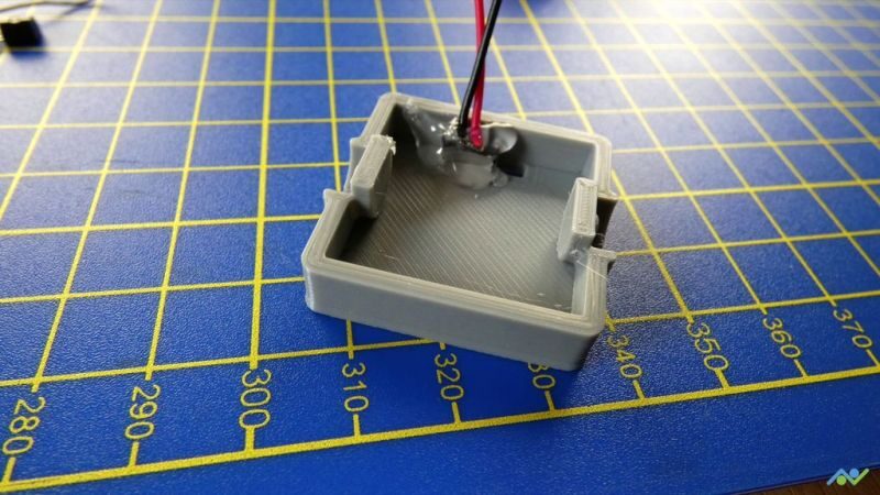
3. 3D Printing the Shell

This shell was initially only able to accommodate the OLED module. Finally, by modifying the Piksey Pico, I was able to fit all components inside. If you are using an Arduino Nano or UNO, then the shell can only accommodate the display; other electronic devices must be placed outside.
4. Wiring Test

The wiring method can be adjusted according to your habits. In the project, I used multi-strand wire, which worked well. The final wiring method may differ slightly from mine based on your actual situation.


After completing the wiring, start testing to ensure everything is normal before proceeding with assembly.
5. Assembling All Components

Finally, after all components are installed, close the shell. Be careful not to apply too much force on the OLED module during installation to avoid damage.

So far, the entire project is complete. This project is very simple and suitable for beginner electronics enthusiasts. If you happen to have a spare Arduino board and a DS18B20, go ahead and make one!

Community: MAKE Fun Unlimited
Project source: https://make.quwj.com/project/180
