Troubleshooting and working principle of the magnetic safety sensor, model, and wiring
1. Fault
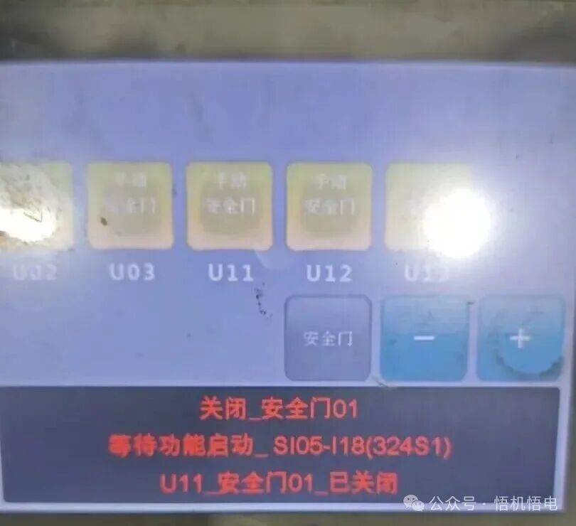
2. Based on the alarm prompt, it may be a signal issue. Check the device I/O and find that after the door lock is closed, the corresponding signal 324S1 of the magnetic safety sensor is not 1, and the green indicator light is not on. (This photo was taken in normal state)
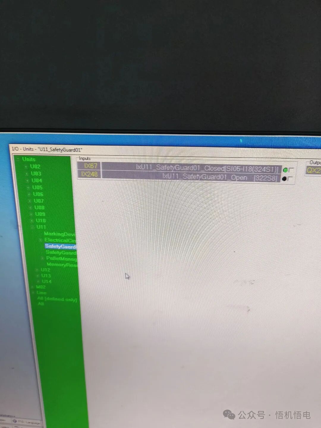
3. Check that the sensor wires and connectors are normal. Replace the lower part of the magnetic safety sensor (the part with the connector below), the magnetic head (the upper part) was not replaced. Then monitor the input signal 324S1 when opening and closing the door, which is normal.
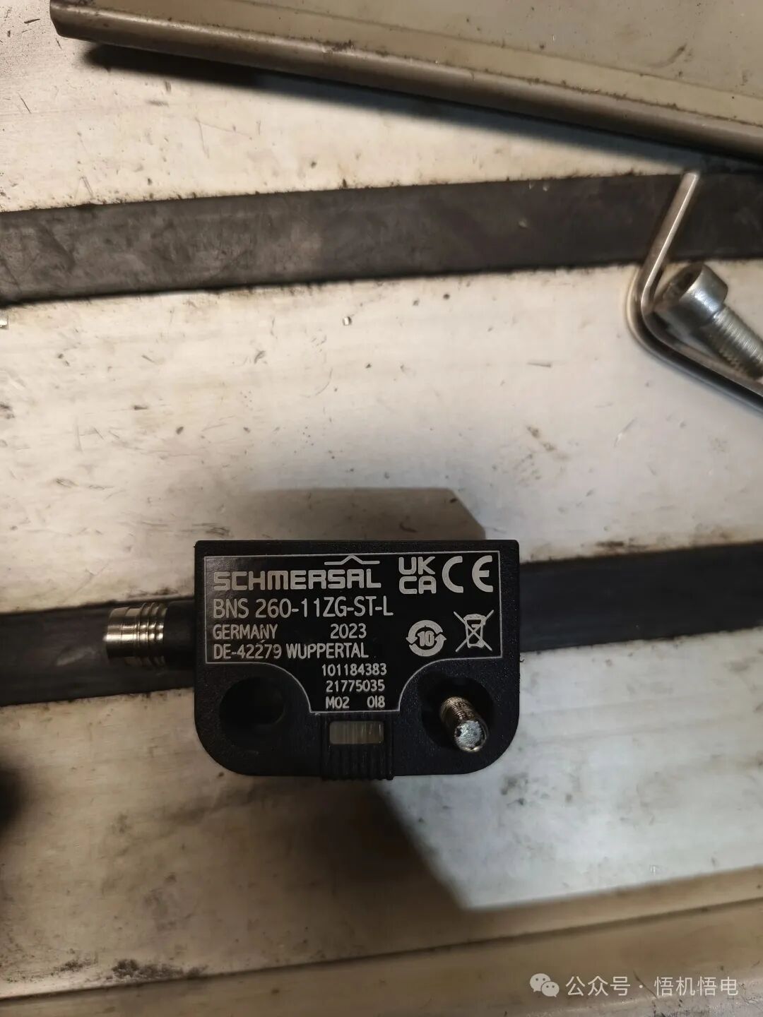
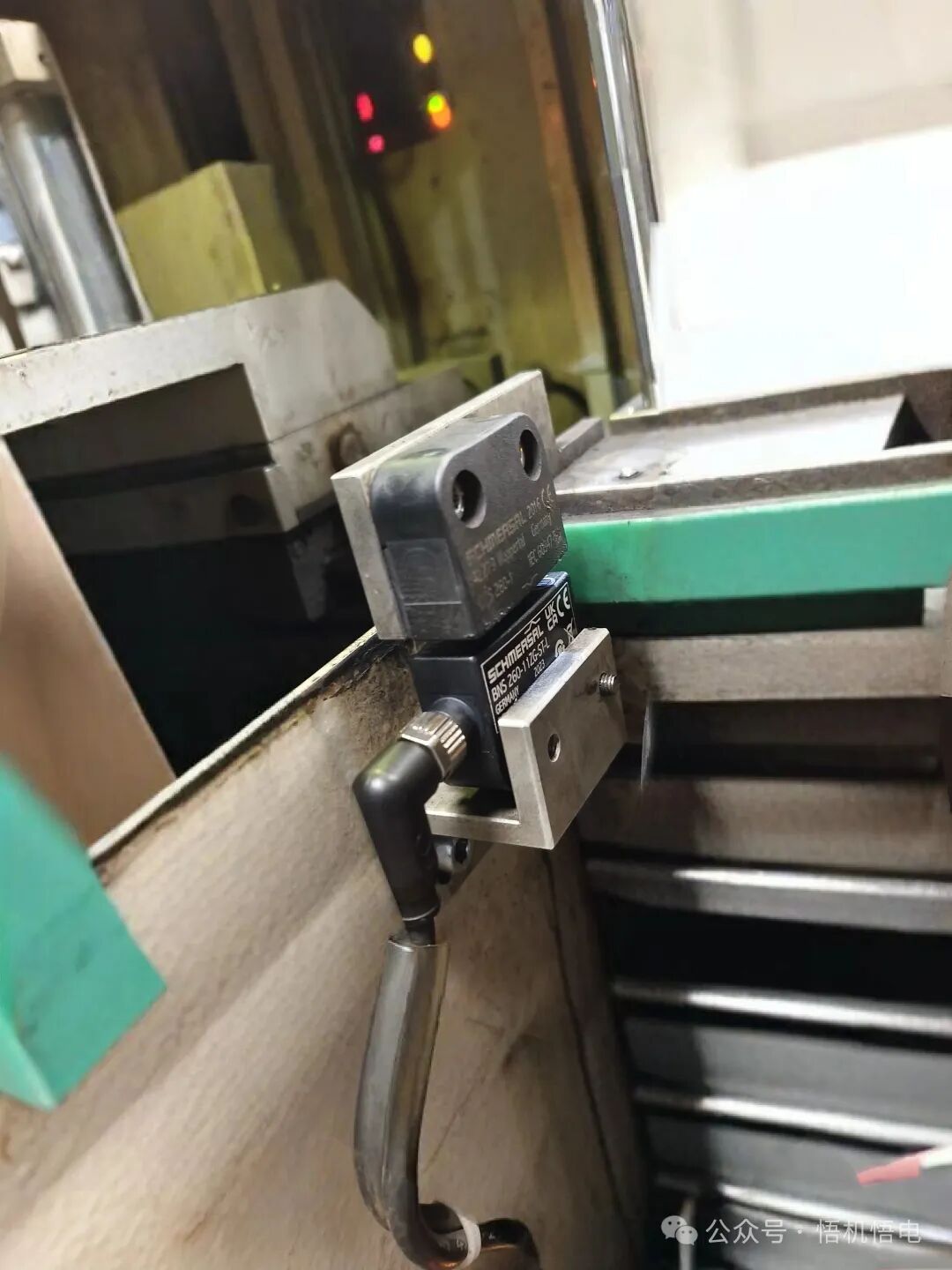
4. Working principle of the magnetic safety sensor: This sensor consists of two parts, one part is the magnetic head, and the other part is the sensing output part. The two parts work in coupling, and this sensor has two or more switch signals. The switch signals are connected to a multi-channel safety relay. After the door is closed normally, the module outputs a switch signal, which provides safer and more reliable monitoring of the safety door status, protecting personal safety.
5. Model: BNS 260-①②Z③-④-⑤-⑥
① 11 represents one normally open NO and one normally closed NC
02 represents two normally closed NC
② None represents with monitoring output
/01 represents one NC
③ None represents no indicator light
G represents with LED switch status display
④ None represents pre-wired cable
ST represents with connecting plug
⑤ L represents left side door hinge installation (fixed, magnetic head installed on the hinge side active)
R represents right side door hinge installation
⑥ 2750 adjustable safety distance
The sensor in this fault is equipped with one normally open and one normally closed, with LED indicator light. When the door is closed, the LED is on, and when the door is open, the LED indicator light is off.
6. Plug definition and wiring
1. Pin numbering of various model male connectors M8, 4-pin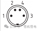 M 8 mm, 6-pin
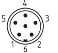 M12, 4-pin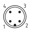
2. Wiring corresponding to each model of the sensor
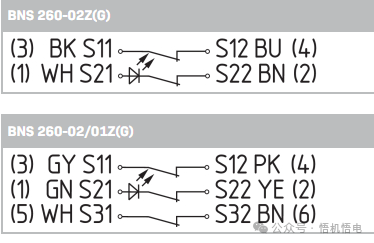
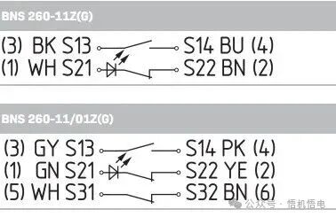
The numbers in parentheses are the pin numbering of the plug, and the letters represent wire colors. S with numbers represents the contact numbering of the safety relay module.
3. Corresponding wiring of the safety relay module
Safety contacts S21-S22 and S11-S12 or S13-S14
Signal contacts S31-S32
4. Safety module wiring: s21 and s22 one channel, s13 and s14 one channel BNS 260-11Z is the magnetic safety sensor SRB is the safety relay BNS-Y is the Y-shaped connector (used to connect multiple sensors back to the safety relay module)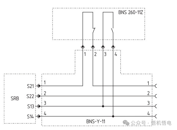 Safety module wiring: s21 and s22 one channel, s11 and s12 one channel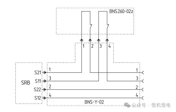
Note: Refer to the official website. If there is any infringement, please contact for deletion. Any shortcomings are welcome for guidance.