@[toc]
https://github.com/wdfk-prog/RT-Thread-Study
28 I2C Driver
https://www.i2c-bus.org/i2c-primer/termination-versus-capacitance/
28.0 Hardware Circuit

The I2C bus uses SDA and SCL to transmit data and clock. First, it is important to realize that SDA and SCL are open-drain (also known as open-collector in the TTL world), meaning that I2C master and slave devices can only drive these lines low or leave them floating. If no I2C device pulls it low, the termination resistor Rp will pull the line high to Vcc. This allows multiple I2C masters to operate simultaneously (if they have **multi-master capability) or clock stretching (slaves can slow down communication by holding SCL low).
The termination resistor Rp, along with the line capacitance Cp, affects the timing behavior of signals on SDA and SCL. While I2C devices use open-drain drivers or FETs to pull the lines low (typically capable of driving at least about 10mA or more), the pull-up resistor Rp is responsible for restoring the signal to a high level. Rp is typically between 1 kΩ and 10 kΩ, resulting in a typical pull-up current of about 1 mA or less. This is why I2C signals have a sawtooth appearance. In fact, each “tooth” shows the charging characteristics of the line on the rising edge and the discharging characteristics on the falling edge.
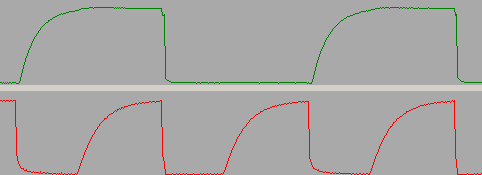
Rp = 10 kΩ and Cp = 300 pF for SDA (top) and SCL (bottom). The SCL clock runs at 100 kHz (nominal).
28.1 I2C Device Driver
28.1.1 I2C Device Registration
- 1. Call
<span>rt_i2c_bus_device_device_init</span>to register the I2C device to rt_device
struct rt_i2c_bus_device_ops
{
    rt_ssize_t (*master_xfer)(struct rt_i2c_bus_device *bus,
                             struct rt_i2c_msg msgs[],
                             rt_uint32_t num);
    rt_ssize_t (*slave_xfer)(struct rt_i2c_bus_device *bus,
                            struct rt_i2c_msg msgs[],
                            rt_uint32_t num);
    rt_err_t (*i2c_bus_control)(struct rt_i2c_bus_device *bus,
                                int cmd,
                                void *args);
};

struct rt_i2c_bus_device
{
    struct rt_device parent;
    const struct rt_i2c_bus_device_ops *ops;
    rt_uint16_t flags;
    struct rt_mutex lock;
    rt_uint32_t timeout;
    rt_uint32_t retries;
    void *priv;
};

rt_err_t rt_i2c_bus_device_device_init(struct rt_i2c_bus_device *bus,
                                       const char *name)
{
    // Register bus device
    device->user_data = bus;
    // Hook read/write control functions
    device->init    = RT_NULL;
    device->open    = RT_NULL;
    device->close   = RT_NULL;
    device->read    = i2c_bus_device_read;
    device->write   = i2c_bus_device_write;
    device->control = i2c_bus_device_control;
}
28.2 I2C Bus Device Driver
28.2.1 Initialization
- • Initialize bus mutex
rt_err_t rt_i2c_bus_device_register(struct rt_i2c_bus_device *bus,
                                    const char *bus_name)
{
    // Initialize lock
    rt_mutex_init(&bus->lock, "i2c_bus_lock", RT_IPC_FLAG_PRIO);
    // Default timeout according to one switching time
    if (bus->timeout == 0) bus->timeout = RT_TICK_PER_SECOND;
    // Register I2C device, hook read/write control functions
    res = rt_i2c_bus_device_device_init(bus, bus_name);
    return res;
}
28.2.2 Transfer
- • Lock to form a critical section, call
<span>master_xfer</span>function to complete I2C data transfer
    err = rt_mutex_take(&bus->lock, RT_WAITING_FOREVER);
    if (err != RT_EOK)
    {
        return (rt_ssize_t)err;
    }
    ret = bus->ops->master_xfer(bus, msgs, num);
    err = rt_mutex_release(&bus->lock);
- • rt_i2c_master_recv
    msg.flags  = flags | RT_I2C_RD;
    ret = rt_i2c_transfer(bus, &msg, 1);
- • rt_i2c_master_send
    msg.flags = flags;
    ret = rt_i2c_transfer(bus, &msg, 1);
28.2 Software I2C
- • TIMING_DELAY default 10us, i.e., 10kHz
- • TIMING_TIMEOUT default 10 ticks
28.1.1 Initialization
- 1. Initialize I2C pins, set to open-drain output, default high level
    rt_pin_mode(cfg->scl_pin, PIN_MODE_OUTPUT_OD);
    rt_pin_mode(cfg->sda_pin, PIN_MODE_OUTPUT_OD);
    rt_pin_write(cfg->scl_pin, PIN_HIGH);
    rt_pin_write(cfg->sda_pin, PIN_HIGH);
- • Reason:
SDA and SCL are open-drain, meaning that I2C master and slave devices can only drive these lines low or leave them floating. If no I2C device pulls it low, the termination resistor Rp will pull the line high to Vcc.

The termination resistor Rp, along with the line capacitance Cp, affects the timing behavior of signals on SDA and SCL. While I2C devices use open-drain drivers or FETs to pull the lines low (typically capable of driving at least about 10mA or more), the pull-up resistor Rp is responsible for restoring the signal to a high level. Rp is typically between 1 kΩ and 10 kΩ, resulting in a typical pull-up current of about 1 mA or less. This is why I2C signals have a sawtooth appearance. In fact, each "tooth" shows the charging characteristics of the line on the rising edge and the discharging characteristics on the falling edge.
- 2. Call
<span>rt_i2c_bus_device_register</span>to register the I2C bus device, initializing the bus mutex
- • Hook software I2C operation functions to the bus device
struct rt_i2c_bit_ops
{
    void *data;            /* private data for low-level routines */
    void (*set_sda)(void *data, rt_int32_t state);
    void (*set_scl)(void *data, rt_int32_t state);
    rt_int32_t (*get_sda)(void *data);
    rt_int32_t (*get_scl)(void *data);
    void (*udelay)(rt_uint32_t us);
    rt_uint32_t delay_us;  /* scl and sda line delay */
    rt_uint32_t timeout;   /* in ticks */
    void (*pin_init)(void);
    rt_bool_t i2c_pin_init_flag;
};

int rt_soft_i2c_init(void)
{
    obj->ops = soft_i2c_ops;
    obj->ops.data = cfg;
    // i2c_bug.priv for rt_i2c_bit_ops
    obj->i2c_bus.priv = &obj->ops;
}
3.<span>i2c_bus_unlock</span> to unlock I2C
- • Deadlock
Bus behavior: SCL is high, SDA remains low
Reason:
Under normal circumstances, the I2C bus protocol ensures normal read and write operations on the bus.

However, when the I2C master device is reset abnormally (due to watchdog action, abnormal power supply on the board causing chip reset, manual button reset, etc.), it may lead to a deadlock on the I2C bus. Below is a detailed explanation of the causes of bus deadlock. During the read and write operations of the I2C master device, after the start signal, the master controls SCL to generate 8 clock pulses, then pulls the SCL signal low. At this time, the slave device outputs an acknowledgment signal, pulling the SDA signal low.

If the master device resets abnormally at this time, SCL will be released to high. If the slave device does not reset, it will continue to acknowledge I2C, keeping SDA low until SCL goes low, which will end the acknowledgment signal.

For the I2C master device, after reset, it checks the SCL and SDA signals. If it finds that the SDA signal is low, it will assume that the I2C bus is occupied and will wait for the SCL and SDA signals to go high.

Thus, the I2C master device waits for the slave device to release the SDA signal, while the I2C slave device is waiting for the master device to pull the SCL signal low to release the acknowledgment signal, both waiting for each other, leading to a deadlock state on the I2C bus.

Similarly, when I2C performs a read operation, if the I2C slave device acknowledges and outputs data, if the I2C master device resets abnormally at this moment and the data bit being output by the I2C slave device happens to be 0, it will also lead to a deadlock state on the I2C bus.

Thus, the master and slave enter a deadlock process of mutual waiting.
Solution:
Deadlock resolution method

    Add an I2C bus recovery procedure in the I2C master device. After each reset of the I2C master device, if it detects that the SDA data line is pulled low, it controls the SCL clock line to generate 9 clock pulses (for the case of 8-bit data), so that the I2C slave device can complete the pending read operation and recover from the deadlock state.

    This method has significant limitations because most master devices' I2C modules are implemented by built-in hardware circuits, and software cannot directly control the SCL signal to simulate the required clock pulses.
/**
* if i2c is locked, this function will unlock it
*
* @param i2c config class.
*
* @return RT_EOK indicates successful unlock.
*/
static rt_err_t i2c_bus_unlock(const struct soft_i2c_config *cfg)
{
    rt_ubase_t i = 0;
    // After reset, if SDA is low, generate 9 clock pulses
    if (PIN_LOW == rt_pin_read(cfg->sda_pin))
    {
        while (i++ < 9)
        {
            rt_pin_write(cfg->scl_pin, PIN_HIGH);
            rt_hw_us_delay(cfg->timing_delay);
            rt_pin_write(cfg->scl_pin, PIN_LOW);
            rt_hw_us_delay(cfg->timing_delay);
        }
    }
    // Still low deadlock state, return error
    if (PIN_LOW == rt_pin_read(cfg->sda_pin))
    {
        return -RT_ERROR;
    }
    return RT_EOK;
}
28.1.2 Read/Write i2c_bit_xfer
#define RT_I2C_WR              0x0000        /* Write flag, cannot be ORed with read flag */
#define RT_I2C_RD              (1u << 0)     /* Read flag, cannot be ORed with write flag */
#define RT_I2C_ADDR_10BIT      (1u << 2)     /* 10-bit address mode */
#define RT_I2C_NO_START        (1u << 4)     /* No start condition */
#define RT_I2C_IGNORE_NACK     (1u << 5)     /* Ignore NACK */
#define RT_I2C_NO_READ_ACK     (1u << 6)     /* Do not send ACK when reading */
#define RT_I2C_NO_STOP         (1u << 7)     /* Do not send stop bit */

static rt_ssize_t i2c_bit_xfer(struct rt_i2c_bus_device *bus,
                              struct rt_i2c_msg msgs[],
                              rt_uint32_t num)
{
    for (i = 0; i < num; i++)
    {
        msg = &msgs[i];
        ignore_nack = msg->flags & RT_I2C_IGNORE_NACK;
        // Send start condition
        if (!(msg->flags & RT_I2C_NO_START))
        {
            if (i)
            {
                // Send repeated start condition
                i2c_restart(ops);
            }
            else
            {
                LOG_D("send start condition");
                i2c_start(ops);
            }
            // Send address
            ret = i2c_bit_send_address(bus, msg);
            if ((ret != RT_EOK) && !ignore_nack)
            {
                LOG_D("receive NACK from device addr 0x%02x msg %d",
                        msgs[i].addr, i);
                goto out;
            }
        }
        // Read data
        if (msg->flags & RT_I2C_RD)
        {
            ret = i2c_recv_bytes(bus, msg);
            if (ret >= 1)
            {
                LOG_D("read %d byte%s", ret, ret == 1 ? "" : "s");
            }
            if (ret < msg->len)
            {
                if (ret >= 0)
                    ret = -RT_EIO;
                goto out;
            }
        }
        // Send data
        else
        {
            ret = i2c_send_bytes(bus, msg);
            if (ret >= 1)
            {
                LOG_D("write %d byte%s", ret, ret == 1 ? "" : "s");
            }
            if (ret < msg->len)
            {
                if (ret >= 0)
                    ret = -RT_ERROR;
                goto out;
            }
        }
    }
    ret = i;

out:
    if (!(msg->flags & RT_I2C_NO_STOP))
    {
        LOG_D("send stop condition");
        // Send stop condition
        i2c_stop(ops);
    }
    return ret;
}
28.1.3 i2c_start
static void i2c_start(struct rt_i2c_bit_ops *ops)
{
    // Before starting, the I2C bus should be in idle state, i.e., both SDA and SCL are high
#ifdef RT_I2C_BITOPS_DEBUG
    if (ops->get_scl && !GET_SCL(ops))
    {
        LOG_E("I2C bus error, SCL line low");
    }
    if (ops->get_sda && !GET_SDA(ops))
    {
        LOG_E("I2C bus error, SDA line low");
    }
#endif
    // When SCL line is high, SDA line switches from high to low to indicate start condition
    SDA_L(ops);
    i2c_delay(ops);
    SCL_L(ops);
}
28.1.4 i2c_restart
static void i2c_restart(struct rt_i2c_bit_ops *ops)
{
    SDA_H(ops);
    SCL_H(ops);
    i2c_delay(ops);
    SDA_L(ops);
    i2c_delay(ops);
    SCL_L(ops);
}
28.1.5 i2c_stop
static void i2c_stop(struct rt_i2c_bit_ops *ops)
{
    // When SCL is high, SDA line switches from low to high to indicate stop condition.
    SDA_L(ops);
    i2c_delay(ops);
    SCL_H(ops);
    i2c_delay(ops);
    SDA_H(ops);
    i2c_delay2(ops);
}
28.1.6 i2c_writeb
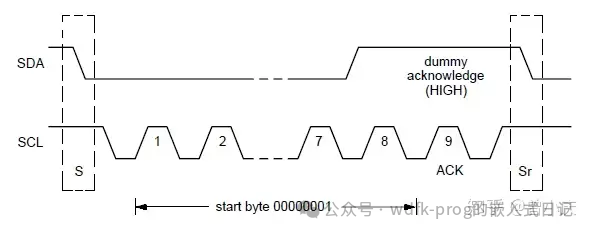
- • Send data from high bit to low bit, send one byte of data, wait for ACK
- • Each bit is sent by SDA, low level indicates 0, high level indicates 1; send one bit at a time, wait for SCL to be high before sending the next bit
    for (i = 7; i >= 0; i--)
    {
        SCL_L(ops);
        bit = (data >> i) & 1;
        SET_SDA(ops, bit);
        i2c_delay(ops);
        if (SCL_H(ops) < 0)
        {
            LOG_D("i2c_writeb: 0x%02x, "
                    "wait scl pin high timeout at bit %d",
                    data, i);
            return -RT_ETIMEOUT;
        }
    }
    SCL_L(ops);
    i2c_delay(ops);
    return i2c_waitack(ops);
28.1.7 i2c_waitack
- • Wait for ACK; read SDA level when SCL is high, ACK is low, NACK is high
rt_inline rt_bool_t i2c_waitack(struct rt_i2c_bit_ops *ops)
{
    rt_bool_t ack;
    SDA_H(ops);
    i2c_delay(ops);
    if (SCL_H(ops) < 0)
    {
        LOG_W("wait ack timeout");
        return -RT_ETIMEOUT;
    }
    ack = !GET_SDA(ops);    /* ACK : SDA pin is pulled low */
    LOG_D("%s", ack ? "ACK" : "NACK");
    SCL_L(ops);
    return ack;
}
28.1.8 i2c_readb
- • Receive data from high bit to low bit, receive one byte of data
- • Must read SDA level during SCL high
static rt_int32_t i2c_readb(struct rt_i2c_bus_device *bus)
{
    rt_uint8_t i;
    rt_uint8_t data = 0;
    struct rt_i2c_bit_ops *ops = (struct rt_i2c_bit_ops *)bus->priv;
    SDA_H(ops);
    i2c_delay(ops);
    for (i = 0; i < 8; i++)
    {
        data <<= 1;
        if (SCL_H(ops) < 0)
        {
            LOG_D("i2c_readb: wait scl pin high "
                    "timeout at bit %d", 7 - i);
            return -RT_ETIMEOUT;
        }
        if (GET_SDA(ops))
            data |= 1;
        SCL_L(ops);
        i2c_delay2(ops);
    }
    return data;
}
28.1.9 i2c_bit_send_address
    /* 7-bit addr */
    addr1 = msg->addr << 1;
    if (flags & RT_I2C_RD)
        addr1 |= 1;
    for (i = 0; i <= retries; i++)
    {
        ret = i2c_writeb(bus, addr);
        if (ret == 1 || i == retries)
            break;
        LOG_D("send stop condition");
        i2c_stop(ops);
        i2c_delay2(ops);
        LOG_D("send start condition");
        i2c_start(ops);
    }
28.1.10 i2c_recv_bytes
while (count > 0)
{
    val = i2c_readb(bus);
    if (val >= 0)
    {
        *ptr = val;
        bytes++;
    }
    else
    {
        break;
    }
    ptr++;
    count--;
    LOG_D("receive bytes: 0x%02x, %s",
            val, (flags & RT_I2C_NO_READ_ACK) ?
            "(No ACK/NACK)" : (count ? "ACK" : "NACK"));
    if (!(flags & RT_I2C_NO_READ_ACK))
    {
        val = i2c_send_ack_or_nack(bus, count);
        if (val < 0)
            return val;
    }
}
28.1.11 i2c_send_ack_or_nack
- • Send ACK or NACK when SCL is high
static rt_err_t i2c_send_ack_or_nack(struct rt_i2c_bus_device *bus, int ack)
{
    struct rt_i2c_bit_ops *ops = (struct rt_i2c_bit_ops *)bus->priv;
    if (ack)
        SET_SDA(ops, 0);
    i2c_delay(ops);
    if (SCL_H(ops) < 0)
    {
        LOG_E("ACK or NACK timeout.");
        return -RT_ETIMEOUT;
    }
    SCL_L(ops);
    return RT_EOK;
}
28.3 STM32 HAL I2C
1.<span>HAL_I2C_Mem_Write</span>: Sends device address, also sends register address, then sends data
2.<span>HAL_I2C_Master_Transmit</span>: Sends device address, then sends data
3.<span>HAL_I2C_Master_Seq_Transmit_IT</span>: Communication sequence (Seq) transmission function
28.3.1 Blocking Mode
- • HAL_I2C_Master_Transmit
- 1. Wait for
<span>I2C_FLAG_BUSY</span>to not be set, timeout 25ms
ISR->BUSY This flag indicates that communication is ongoing on the bus. It is set by hardware when a start condition is detected. It is cleared by hardware when a STOP condition or PE=0 is detected.
- 2. Execute different sending methods based on the sending length
->255, use <span>I2C_RELOAD_MODE</span>
- • <=255, use
<span>I2C_AUTOEND_MODE</span>
- 3. Call
<span>I2C_TransferConfig</span>, execute<span>I2C_GENERATE_START_WRITE</span>to write - 4. Wait for
<span>TXIS</span>flag to be set before writing data
Sending transmission status: This bit is set by hardware when the I2C_TXDR register is empty, and the data to be transmitted must be written to the I2C_TXDR register. It will be cleared when the next data to be sent is written to the I2C_TXDR register.
- 5. If data is >255, multiple writes are needed, wait for
<span>I2C_FLAG_TCR</span>flag to be set, then execute sending again - 6. After finishing, wait for
<span>STOPF</span>flag to be set, send stop condition
- • HAL_I2C_Master_Receive
28.3.2 Non-blocking Interrupt Mode
- • HAL_I2C_Master_Transmit_IT
- 1. Set ISR callback function
<span>I2C_Master_ISR_IT</span> - 2. Send device address
- 3. Enable
<span>enable ERR, TC, STOP, NACK, TXI interrupts</span> - 4. Interrupt service function
<span>HAL_I2C_EV_IRQHandler</span>-><span>I2C_Master_ISR_IT</span>
Determine from the interrupt that data has not been fully sent, continue sending;
After sending is complete, call <span>I2C_ITMasterSeqCplt</span>
- 5. Trigger callback
<span>HAL_I2C_MasterTxCpltCallback</span>
28.3.3 Non-blocking DMA
28.3.4 SEQ Transmission Function
https://blog.csdn.net/NeoZng/article/details/128496694
28.4 Hardware I2C Driver
- 1. IT mode and DMA enable completion quantity for communication; TX and RX use the same completion quantity
Reason: For the master, to receive the required data, it also needs to send a command before executing the reception; therefore, using the same completion quantity does not cause conflicts; for master transmission and reception, non-blocking mode is meaningless, so use completion quantity for communication.