: Recently, I modified an old device that required communication control applications, from which I derived some insights:
1. FX2N-485-BD is economical to use;
A./ (ASCII communication mode, operation, and frequency register address can be easily mistaken, but LRC checksum is easy to obtain)/
B../ (RTU communication mode, operation, and frequency register address is less likely to be mistaken, but CRC checksum is harder to obtain)/
2. Using communication control can eliminate PLC input/output hardware points, using FX2N-485-BD requiresattentionto the correctness of wiring and shielding issues;
3. When selecting programming hardware, it is better to choose 3Uprogramming hardware, if selecting Mitsubishi’s inverter, the command can be directly applied, saving time and effort!
Features
1. Electrical characteristics of RS-485: It uses differential signaling with positive logic, where logic “1” is represented by a voltage difference of +(2~6)V between the two wires; logic “0” is represented by a voltage difference of -(2~6)V. The signal level is lower than that of RS-232-C, making it less likely to damage the interface circuit chips, and this level is compatible with TTL levels, facilitating connection with TTL circuits.
2. The maximum data transmission rate of RS-485 is 10Mbps.
3. The RS-485 interface uses a combination of balanced drivers and differential receivers, enhancing the ability to resist common-mode interference, thus providing good noise immunity.
4. The maximum communication distance of RS-485 is approximately 1219m, with a maximum transmission rate of 10Mbps. The transmission rate is inversely proportional to the transmission distance; the lower the transmission rate, the longer the transmission distance. If a distance longer than the maximum communication distance of RS-485 is required, a 485 repeater must be added. The RS-485 bus generally supports a maximum of 32 nodes, but with special 485 chips, it can reach 128 or 256 nodes, and up to 400 nodes can be supported.
Interface
Edit
RS485 interface forms a half-duplex network, generally using a two-wire system (previously there was a four-wire connection method, which could only achieve point-to-point communication and is rarely used now), mostly using shielded twisted pair for transmission. This wiring method allows for a maximum of 32 nodes on the same bus in a bus topology. In RS-485 communication networks, a master-slave communication method is generally used, where one master controls multiple slaves. In many cases, connecting the RS-485 communication link is simply done by connecting the “A” and “B” ends of each interface with a pair of twisted wires. The RS485 connector uses a DB-9 9-pin plug, with the intelligent terminal RS485 interface using DB-9 (socket), and the keyboard connection RS485 using DB-9 (pin).
Another issue is the signal ground. The above connection method can work normally in many situations, but it hides significant risks for two reasons: (1) Common-mode interference: The RS-485 interface uses differential signaling to transmit signals and does not require detection relative to a reference point; the system only needs to detect the potential difference between the two wires. However, people often overlook that the transceiver has a certain common-mode voltage range, which is -7 to +12V for RS-485 transceivers. Only when this condition is met can the entire network operate normally. When the common-mode voltage in the network line exceeds this range, it can affect the stability and reliability of communication, even damaging the interface. (2) EMI (Electromagnetic Interference) issue: The common-mode part of the signal output by the driver needs a return path; without a low-resistance return path (signal ground), the common-mode part of the signal will radiate back to the source, making the entire bus act like a large antenna radiating electromagnetic waves.
Since PCs only have RS232 interfaces by default, there are two ways to obtain the RS485 circuit on a PC host: (1) Use an RS232/RS485 conversion circuit to convert the PC’s serial RS232 signal into RS485 signal; for complex industrial environments, it is best to choose products with surge protection and isolation. (2) Use a PCI multi-serial card that directly outputs RS485 type signals.
Cable
Edit
In low-speed, short-distance, and non-interference situations, ordinary twisted pairs can be used; conversely, in high-speed, long-distance transmissions, RS485 dedicated cables (STP-120Ω (for RS485 & CAN) one pair 18 AWG) with impedance matching (generally 120Ω) must be used. In environments with severe interference, armored twisted shielded cables (ASTP-120Ω (for RS485 & CAN) one pair 18 AWG) should be used. When using RS485 interfaces, the maximum cable length allowed for data signal transmission from the RS485 interface to the load is inversely proportional to the baud rate of the signal transmission. This length is mainly affected by signal distortion and noise. Theoretically, when the communication rate is 100Kbps or lower, the maximum transmission distance of RS485 can reach 1200 meters, but in practical applications, the transmission distance may vary due to the characteristics of the chips and cables. During transmission, repeaters can be used to amplify the signal, with a maximum of eight repeaters, meaning that the theoretical maximum transmission distance of RS485 can reach 10.8 kilometers. If long-distance transmission is truly needed, optical fiber can be used as the transmission medium, with a photoelectric converter added at both ends; multimode fiber can achieve a transmission distance of 5 to 10 kilometers, while single-mode fiber can reach up to 50 kilometers.
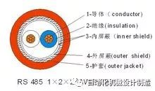 Chengrui RS-485 communication cable structure diagramNetwork layout
Edit
Network topology generally adopts a terminal-matched bus structure, not supporting ring or star networks. When constructing the network, the following points should be noted: (1) Use a twisted pair cable as the bus to connect each node in series; the lead length from the bus to each node should be kept as short as possible to minimize the impact of reflected signals in the lead on the bus signal. Some network connections may work correctly at short distances and low speeds, but as the communication distance increases or the communication rate rises, their adverse effects will become more severe, mainly because signals reflected at the ends of branches will superimpose on the original signal, causing signal quality to degrade. (2) Attention should be paid to the continuity of the bus characteristic impedance; signal reflections will occur at points of impedance discontinuity. The following situations are prone to such discontinuities: different cables are used for different segments of the bus, or too many transceivers are installed too close together on a segment of the bus, or excessively long branch lines are drawn from the bus. Another issue to pay attention to in RS485 networking is the terminal load resistor problem; in cases of short distances and few devices, the network can work well without terminal load resistors, but performance will degrade as distance increases. Theoretically, when sampling at the midpoint of each received data signal, as long as the reflected signal is attenuated to a sufficiently low level at the start of sampling, matching can be disregarded. However, this is difficult to manage in practice. An article from Maxim in the USA mentions an empirical principle that can be used to determine when matching is needed based on data rate and cable length: when the signal transition time (rise or fall time) exceeds three times the time required for the electrical signal to travel unidirectionally along the bus, matching can be disregarded. Generally, terminal matching is done using terminal resistors; RS-485 should connect terminal resistors at both the beginning and end of the bus cable. The terminal resistor in an RS-485 network is 120Ω, which is equivalent to the characteristic impedance of the cable, as most twisted pair cables have a characteristic impedance of about 100 to 120Ω. This matching method is simple and effective, but it has a drawback: the matching resistor consumes a significant amount of power, making it unsuitable for systems with strict power consumption limits. Another more power-efficient matching method is RC matching. By using a capacitor C to block the DC component, most power can be saved. However, selecting the value of capacitor C is challenging, requiring a trade-off between power consumption and matching quality. Another method uses diodes for matching; although this scheme does not achieve true “matching,” it utilizes the clamping effect of diodes to quickly weaken reflected signals, improving signal quality and achieving significant energy savings. In the past two years, some companies have completed the implementation of information technology in certain enterprises, and local area networks have been laid out in factories extending to every office and control room, introducing serial servers to replace multi-serial cards. This mainly utilizes existing local area network resources to reduce wiring investment and save costs, effectively placing multi-serial cards on-site via TCP/IP.
Length
Edit
When using RS485 interfaces, the maximum cable length allowed for data signal transmission from the generator to the load is a function of the data signal rate, and this length is mainly limited by signal distortion and noise. The maximum cable length versus signal rate relationship curve shown below is derived using 24AWG copper core twisted telephone cable (with a diameter of 0.51mm), a bypass capacitance of 52.5PF/M, and a terminal load resistance of 100 ohms. (The curve is referenced from GB11014-89 Appendix A). As can be seen from the figure, when the data signal rate is reduced to below 90Kbit/S, assuming the maximum allowable signal loss is 6dBV, the cable length is limited to 1200M. In practice, the curve shown is quite conservative, and it is entirely possible to achieve greater cable lengths. When using cables of different diameters, the maximum cable lengths obtained will differ. For example, when the data signal rate is 600Kbit/S, using 24AWG cable, the maximum cable length is 200m; if using 19AWG cable (with a diameter of 0.91mm), the cable length can exceed 200m; if using 28AWG cable (with a diameter of 0.32mm), the cable length can only be less than 200m.