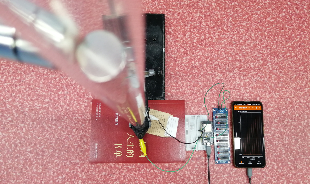
Experimental Scene
1 Introduction
Recently, I have been deeply researching the “hands-on” experiments in the new textbook section on “Electromagnetic Induction,” exploring the relationship between the height of a falling magnet and the maximum induced current in a coil.
The first attempt used a DC ammeter to represent the maximum reading as the peak value of the induced current, resulting in a conclusion that was completely contrary to the experimental expectations.
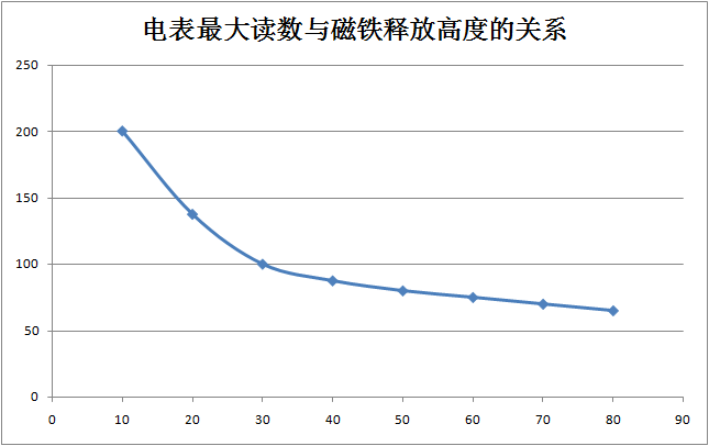 The image obtained during the experiment using a DC ammeter to measure current.
The second attempt utilized a combination of Phyphox, ESP32, and ADS1115 to explore the relationship between the maximum induced current and the height of the falling magnet, achieving relatively satisfactory results. However, two data points clearly deviated from the overall distribution trend, which was quite frustrating.
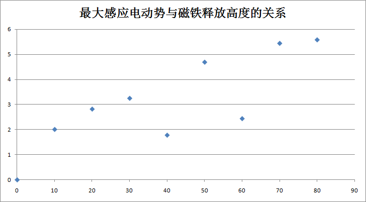 The image obtained during the experiment using a current sensor.
The third attempt involved using the built-in voltage sampling function of the ESP32 to directly measure the peak value of the induced current’s half-cycle generated in the coil during the magnet’s fall. The distribution of data points generally conformed to expected patterns, but the data points exhibited considerable dispersion.
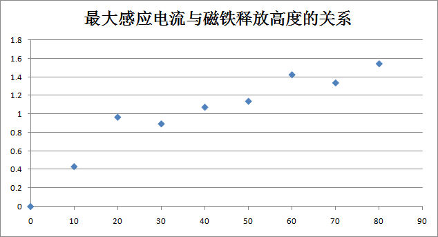 The image obtained during the experiment using the ESP32 to measure current.
2 Early Research from the WeChat Public Account “Physics in Henan”
Using Phyphox, ESP32, and ADS1115 to explore the relationship between the maximum induced current and the height of the falling magnet is not suitable for verification or exploration of Faraday’s electromagnetic induction law. Using Phyphox, ESP32, and ADS1115 to conduct experiments on Lenz’s law.
3 Experimental Reflection and Optimization
The reason for the considerable data dispersion when measuring current with sensors is due to the rapid changes in induced current, which is caused by the low sampling frequency of the sensor. To reduce the dispersion of data points and improve the reliability of the experiment, the experimental plan must be optimized by extending the electromagnetic induction process and increasing the sensor’s sampling frequency. After consulting experts, it was found that when the induced current data is transmitted to a smartphone via Bluetooth, the transmission frequency is only 100Hz, making it difficult to increase the transmission frequency in a short time, or it may require higher technical support. I approached the optimization from the perspective of extending the electromagnetic induction process. The first idea was to tilt the tube to reduce the speed of the magnet passing through the coil by diminishing the effect of gravity; the second idea was to use a stronger magnet with a larger spatial distribution to increase the area for generating induced current. When attempting to reduce gravity, the results were not ideal, which is worth investigating. However, when using a longer and stronger neodymium magnet for the experiment, after multiple trials, I finally achieved satisfactory results.
4 Experimental Exploration
In this experiment, I used a newly purchased transparent hard acrylic tube and a new neodymium magnet. The inner diameter of the solenoid is 22mm, the outer diameter of the new acrylic tube is 22mm, the inner diameter is 18mm, and the diameter of the new neodymium magnet is 15mm with a thickness of 10mm. During the experiment, I found that the performance of a single neodymium magnet was poor, with a high degree of data point dispersion. After careful analysis, it was discovered that the neodymium magnet was oriented horizontally under the influence of the Earth’s magnetic field, causing it to collide with the tube wall while falling, leading to randomness in its orientation as it passed through the solenoid. When using six magnets for the experiment, the total length of the magnets matched the length of the solenoid, and the data curve showed slight deviations from expectations. After multiple attempts, it was found that three neodymium magnets grouped together, forming a new magnet with a diameter of 15mm and a length of 30mm, yielded the best experimental results.
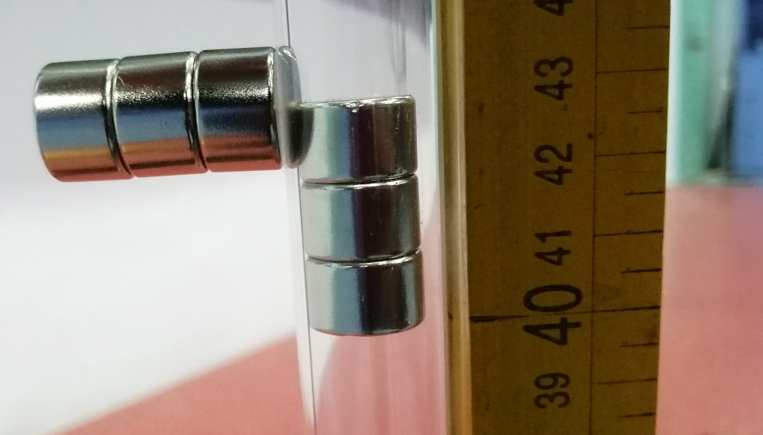 Positioning and releasing the magnet.
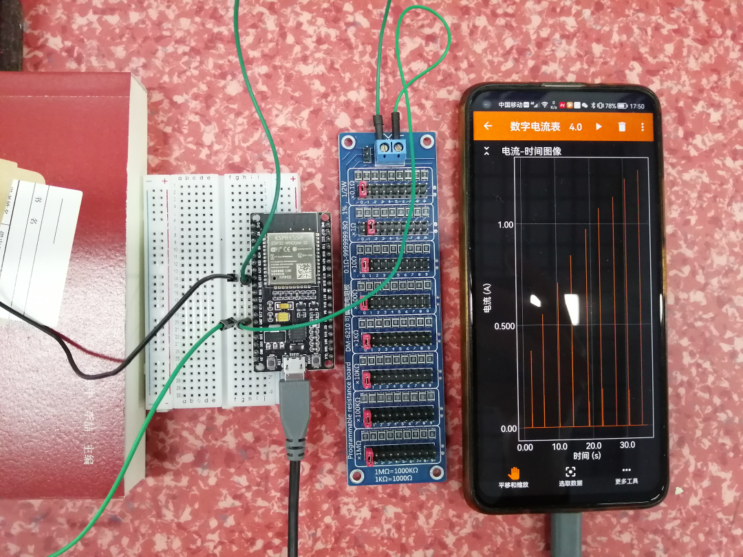 Induced current data collection.
 Induced current data collection.
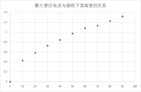
 Relationship between the peak value of induced current and the height of the magnet’s release.
 Relationship between the peak value of induced current and the square root of the height of the magnet’s release.
5 ReflectionsThis experiment lasted two weeks, repeated five to six times, with upgraded experimental equipment, optimized experimental plans, and improved sensor-related technologies, ultimately transforming a qualitative exploratory experiment that could not be conducted using a DC ammeter into a quantitative exploratory experiment based on smartphone sensors.The charm of experimental innovation is boundless, and technological progress is endless.