Click the blue text above to follow us


Gift for Readers

👨💻 Scientific research involves a profound system of thought, requiring researchers to be logical, diligent, and serious. However, effort alone is not enough; leveraging resources is often more important. Additionally, one must have innovative and inspirational points to look up to the stars. It is recommended that readers browse in the order of the table of contents to avoid suddenly falling into a dark maze and losing their way back. This article may not reveal all the answers to your questions, but if it can clarify some doubts that arise in your mind, it could create a beautiful sunset view. If it brings you a storm in your spiritual world, then take the opportunity to wash away the dust that has settled on your ‘lying flat’ state.
Perhaps, after the rain, the sky will be clearer…🔎🔎🔎


1 Overview

Abstract: This paper presents a method for estimating the six degrees of freedom position and attitude of a quadrotor drone by integrating an Inertial Measurement Unit (IMU) and a low-cost Real-Time Kinematic (RTK) GPS unit (considering time delay). Under known time delay conditions, the Delayed Kalman Filter (DKF) is used to fuse the time-lagged GPS position measurements with synchronized attitude and angular velocity measurements from the IMU to achieve accurate state estimation. The effectiveness of the proposed method is validated through numerical examples and experimental data.
1. Introduction
Drones have been widely used in various fields, and the key to their autonomous navigation and control capabilities lies in the precise estimation of their own state. The state of a drone typically includes information such as position, velocity, and attitude, which can be affected by various noise and disturbances, such as sensor measurement errors, airflow disturbances, and GPS signal degradation. To obtain reliable state estimates, effective filtering algorithms are needed to process and fuse sensor data.
The Kalman filter, as an optimal estimation method, has become an ideal choice for drone state estimation due to its ability to effectively handle noise in linear Gaussian systems and its low computational complexity. However, traditional Kalman filters face output delay issues in practical applications, which can lead to estimation errors. To address this problem, researchers have proposed the Delayed Kalman Filter (DKF).
This paper will further explore the DKF-based state estimation method for drones, achieving precise estimation of the six degrees of freedom position and attitude of a quadrotor drone by integrating IMU and RTK GPS units while considering time delays.
2. System Architecture and Sensor Introduction
2.1 System Architecture
The system mainly includes an IMU, RTK GPS unit, data processing unit, and drone flight control system. The IMU provides acceleration and angular velocity information for the drone, while the RTK GPS unit provides position information (considering time delays). The data processing unit is responsible for fusing sensor data and performing state estimation, and the drone flight control system conducts flight control based on the state estimation results.
2.2 Introduction to IMU
IMU stands for Inertial Measurement Unit, a device that integrates accelerometers and gyroscopes. The IMU can provide three-dimensional acceleration and angular velocity information. This information can be used to determine the object’s attitude by combining acceleration data and gyroscope data, thus achieving real-time motion tracking. In drones, the primary role of the IMU is to help maintain balance and attitude.
2.3 Introduction to RTK GPS Unit
The RTK GPS unit is a sensor capable of providing high-precision position information. However, due to factors such as signal propagation delay and processing time of the receiving device, the position information provided by the RTK GPS unit often has a certain time delay. In this system, we consider the time delay of GPS and fuse it with IMU data to achieve more accurate state estimation.
3. DKF-Based State Estimation Method
3.1 DKF Principle
The Delayed Kalman Filter (DKF) is an improvement and extension of the traditional Kalman filter, which reduces the filter’s delay by introducing delayed state and measurement data. Specifically, DKF uses a sliding window approach to store the most recent state and measurement data, and then estimates the current system state by performing a weighted average of the data within the window.
3.2 State Space Model
The state space model of a drone typically includes state variables such as position, velocity, and attitude. In this system, we adopt a six-degree-of-freedom state space model to describe the motion state of the drone. The state variables include the drone’s three-dimensional position, three-dimensional velocity, and attitude angles (pitch angle, roll angle, yaw angle).
3.3 Sensor Data Fusion
Under known time delay conditions, we use DKF to fuse the time-lagged GPS position measurements with the synchronized attitude and angular velocity measurements from the IMU. The fusion process includes prediction and update steps: in the prediction step, the current state is predicted based on the drone’s dynamics model and the previous state estimate; in the update step, the predicted state is corrected using measurements from GPS and IMU.
3.4 Algorithm Implementation
During the algorithm implementation, the following aspects need to be considered:
-
Establishing the state prediction equation: Establish the state prediction equation based on the drone’s dynamics model.
-
Establishing the covariance prediction equation: Establish the covariance prediction equation based on the state prediction equation and noise statistical characteristics.
-
Calculating the Kalman gain: Calculate the Kalman gain based on the covariance prediction equation and measurement noise statistical characteristics.
-
Establishing the state update equation: Correct the predicted state using the Kalman gain and measurement data.
-
Establishing the covariance update equation: Update the covariance matrix based on the state update equation and Kalman gain.
4. Experimental Verification and Result Analysis
4.1 Experimental Setup
To verify the effectiveness of the proposed method, we conducted numerical simulation experiments and outdoor autonomous flight experiments. In the numerical simulation experiments, we simulated the flight process of the drone and added noise and delays; in the outdoor autonomous flight experiments, we used a quadrotor drone integrated with IMU and RTK GPS units for state estimation.
4.2 Result Analysis
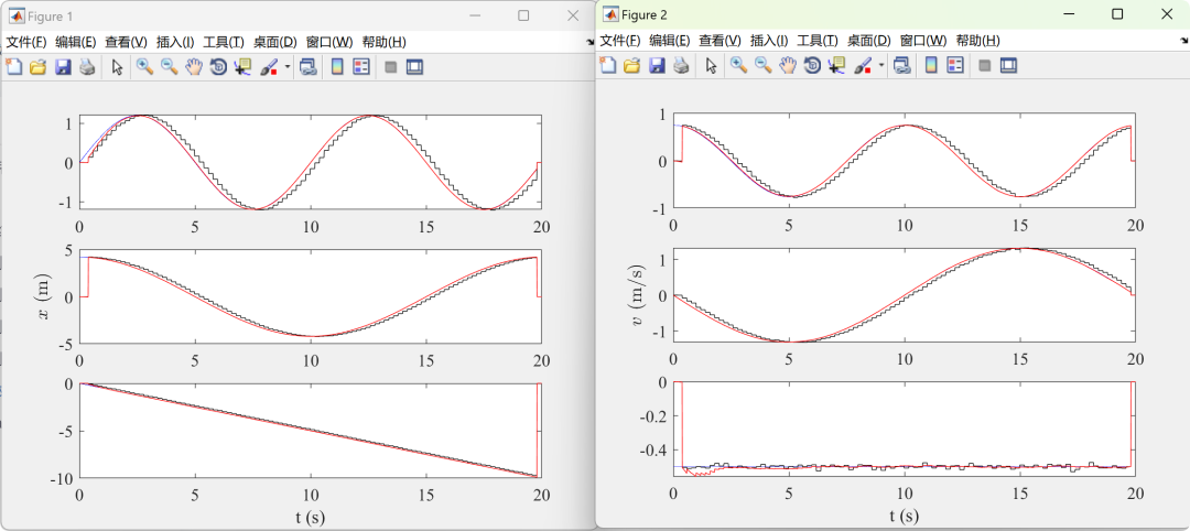
The results of both the numerical simulation experiments and outdoor autonomous flight experiments indicate that the proposed method can effectively fuse IMU and GPS data to achieve precise estimation of the drone’s six degrees of freedom position and attitude. Compared to traditional Kalman filters, DKF can significantly reduce estimation errors and improve estimation accuracy and robustness.
5. Conclusion and Outlook
This paper presents a DKF-based state estimation method for drones, achieving precise estimation of the six degrees of freedom position and attitude of a quadrotor drone by integrating IMU and RTK GPS units while considering time delays. The experimental results demonstrate that the proposed method has high estimation accuracy and robustness.
Future work could further explore more advanced filtering algorithms, such as the Unscented Kalman Filter (UKF) or Particle Filter, to further enhance the performance of drone state estimation. Additionally, other types of sensors, such as visual sensors, could be considered for integration with IMU and GPS to achieve more comprehensive and accurate state estimation.


2 Operating Results


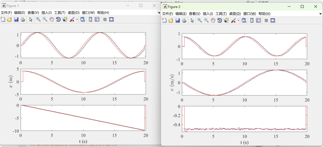
2.1 Example 1 – DKF

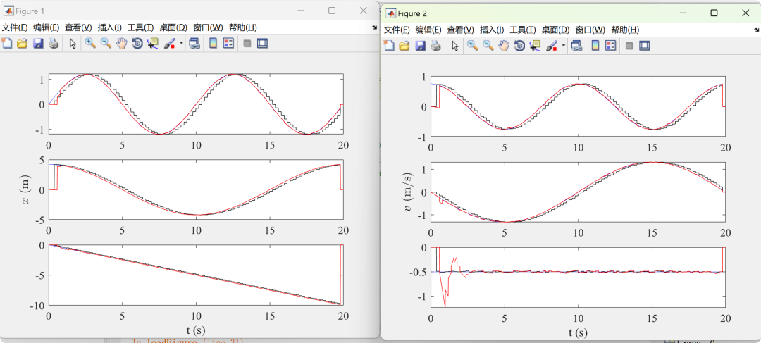
2.2 Example 2 – DKF – Alexander

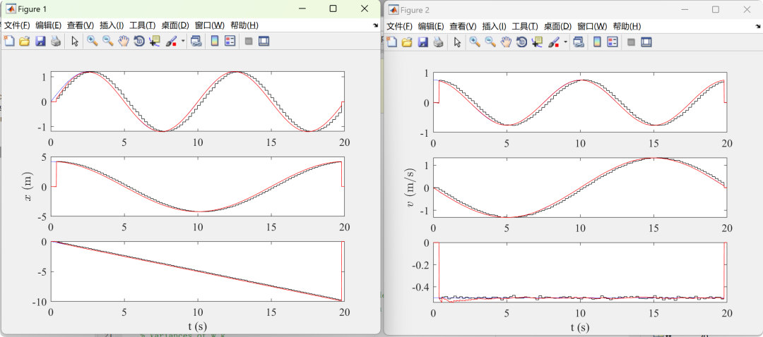
2.3 Example 3 – DKF – Larsen

2.4 Example 4 – DKF – Merwe
部分代码:

addpath('common_functions/');  % includes hat, vee, etc
%% Define variables
tf = 20;  % final time
freq = 100;  % frequency of the system (Hz)
freq_gps = 5;  % frequency of the GPS update (Hz)

% Parameters
R_fv = eye(3);
R_nv = eye(3);
R_bi = [cos(pi/4), -sin(pi/4), 0;
    sin(pi/4), cos(pi/4), 0;
    0, 0, 1];
R_bi = eye(3);

gps_delay = 0.2;  % GPS measurement delay (this code is hard coded
    % such that this delay must be a multiplication of freq_gps)

% Variances of w_k
V_a = 1e-1*diag([0.1 0.1 0.1]).^2;  % acceleration
V_W = 1e-1*diag([0.5 0.5 0.5]).^2;  % angular velocity
V_b_a = 0.01^2;  % acclerometer z bias

Q = blkdiag(V_a, V_W, V_b_a);

% Covariances of measurement error
V_R_imu = diag([0.01 0.01 0.01]).^2;
V_x_gps = diag([0.01 0.01 0.01]).^2;
V_v_gps = diag([0.01 0.01 0.01]).^2;

V_x_lidar = 0.01^2;

% Initial covariances of x
P_x = diag([1^2, 1^2, 1^2]);  % position
P_v = diag([1^2, 1^2, 1^2]);  % velocity
P_eta = diag([0.1^2, 0.1^2, 0.1^2]);  % attitude
P_b_a = 1^2;  % accelerometer z bias

P = blkdiag(P_x, P_v, P_eta, P_b_a);
[m, ~] = size(P);

%% Calculate time related parameters
N = tf*freq + 1;
t = linspace(0,tf,N);
h = t(2) - t(1);

%% Create empty arrays to save data
% tru: simulated true data
% imu: simulated IMU measurement with noise
% vcn: simulated Vicon data with noise
% est: estimated data
% gps: simulated GPS data with noise
% ldr: simulated Lidar data with noise
[tru, imu, vcn, est, gps, ~] = create_arrays_to_save_data(N, m);

%% Initial estimates
est.x(:,1) = [0, 0, 0]';
est.v(:,1) = [0, 0, 0]';


3 References

Some content in this article is sourced from the internet, and citations will be provided where applicable. If there are any inaccuracies, please feel free to contact us for removal. (The content of this article is for reference only; actual results may vary)

[1] Chen Huangjie. Design and Implementation of Battery SOC Estimator Based on Dual Kalman Algorithm [D]. Jilin University, 2015. [2] Wang Qiuting, Qi Wei, Xiao Duo. Cycle Life Estimation of Parallel Lithium Battery Packs Based on Dual Kalman Filtering [J]. Information and Control, 2018.
[3] Zhou Fan, Zheng Wei, Wang Zengfu. Real-time Motion Estimation of Mini Multirotor UAV Based on Multi-hybrid Sensor Information Fusion [J]. Robotics, 2015, 37(1): 8.
[4] Wei Wenhui, Zhao Xiangmo, Ge Zhenzhen. GNSS/IMU Combined Positioning Algorithm Considering System Error Compensation of Dynamic Model [J]. Journal of China Highway, 2022, 35(9): 10.


4 MATLAB Code Implementation

Abstract: This paper presents a method for estimating the six degrees of freedom position and attitude of a quadrotor drone by integrating an Inertial Measurement Unit (IMU) and a low-cost Real-Time Kinematic (RTK) GPS unit (considering time delay). Under known time delay conditions, the Delayed Kalman Filter (DKF) is used to fuse the time-lagged GPS position measurements with synchronized attitude and angular velocity measurements from the IMU to achieve accurate state estimation. The effectiveness of the proposed method is validated through numerical examples and experimental data.
1. Introduction
Drones have been widely used in various fields, and the key to their autonomous navigation and control capabilities lies in the precise estimation of their own state. The state of a drone typically includes information such as position, velocity, and attitude, which can be affected by various noise and disturbances, such as sensor measurement errors, airflow disturbances, and GPS signal degradation. To obtain reliable state estimates, effective filtering algorithms are needed to process and fuse sensor data.
The Kalman filter, as an optimal estimation method, has become an ideal choice for drone state estimation due to its ability to effectively handle noise in linear Gaussian systems and its low computational complexity. However, traditional Kalman filters face output delay issues in practical applications, which can lead to estimation errors. To address this problem, researchers have proposed the Delayed Kalman Filter (DKF).
This paper will further explore the DKF-based state estimation method for drones, achieving precise estimation of the six degrees of freedom position and attitude of a quadrotor drone by integrating IMU and RTK GPS units while considering time delays.
2. System Architecture and Sensor Introduction
2.1 System Architecture
The system mainly includes an IMU, RTK GPS unit, data processing unit, and drone flight control system. The IMU provides acceleration and angular velocity information for the drone, while the RTK GPS unit provides position information (considering time delays). The data processing unit is responsible for fusing sensor data and performing state estimation, and the drone flight control system conducts flight control based on the state estimation results.
2.2 Introduction to IMU
IMU stands for Inertial Measurement Unit, a device that integrates accelerometers and gyroscopes. The IMU can provide three-dimensional acceleration and angular velocity information. This information can be used to determine the object’s attitude by combining acceleration data and gyroscope data, thus achieving real-time motion tracking. In drones, the primary role of the IMU is to help maintain balance and attitude.
2.3 Introduction to RTK GPS Unit
The RTK GPS unit is a sensor capable of providing high-precision position information. However, due to factors such as signal propagation delay and processing time of the receiving device, the position information provided by the RTK GPS unit often has a certain time delay. In this system, we consider the time delay of GPS and fuse it with IMU data to achieve more accurate state estimation.
3. DKF-Based State Estimation Method
3.1 DKF Principle
The Delayed Kalman Filter (DKF) is an improvement and extension of the traditional Kalman filter, which reduces the filter’s delay by introducing delayed state and measurement data. Specifically, DKF uses a sliding window approach to store the most recent state and measurement data, and then estimates the current system state by performing a weighted average of the data within the window.
3.2 State Space Model
The state space model of a drone typically includes state variables such as position, velocity, and attitude. In this system, we adopt a six-degree-of-freedom state space model to describe the motion state of the drone. The state variables include the drone’s three-dimensional position, three-dimensional velocity, and attitude angles (pitch angle, roll angle, yaw angle).
3.3 Sensor Data Fusion
Under known time delay conditions, we use DKF to fuse the time-lagged GPS position measurements with the synchronized attitude and angular velocity measurements from the IMU. The fusion process includes prediction and update steps: in the prediction step, the current state is predicted based on the drone’s dynamics model and the previous state estimate; in the update step, the predicted state is corrected using measurements from GPS and IMU.
3.4 Algorithm Implementation
During the algorithm implementation, the following aspects need to be considered:
-
Establishing the state prediction equation: Establish the state prediction equation based on the drone’s dynamics model.
-
Establishing the covariance prediction equation: Establish the covariance prediction equation based on the state prediction equation and noise statistical characteristics.
-
Calculating the Kalman gain: Calculate the Kalman gain based on the covariance prediction equation and measurement noise statistical characteristics.
-
Establishing the state update equation: Correct the predicted state using the Kalman gain and measurement data.
-
Establishing the covariance update equation: Update the covariance matrix based on the state update equation and Kalman gain.
4. Experimental Verification and Result Analysis
4.1 Experimental Setup
To verify the effectiveness of the proposed method, we conducted numerical simulation experiments and outdoor autonomous flight experiments. In the numerical simulation experiments, we simulated the flight process of the drone and added noise and delays; in the outdoor autonomous flight experiments, we used a quadrotor drone integrated with IMU and RTK GPS units for state estimation.
4.2 Result Analysis
The results of both the numerical simulation experiments and outdoor autonomous flight experiments indicate that the proposed method can effectively fuse IMU and GPS data to achieve precise estimation of the drone’s six degrees of freedom position and attitude. Compared to traditional Kalman filters, DKF can significantly reduce estimation errors and improve estimation accuracy and robustness.
5. Conclusion and Outlook
This paper presents a DKF-based state estimation method for drones, achieving precise estimation of the six degrees of freedom position and attitude of a quadrotor drone by integrating IMU and RTK GPS units while considering time delays. The experimental results demonstrate that the proposed method has high estimation accuracy and robustness.
Future work could further explore more advanced filtering algorithms, such as the Unscented Kalman Filter (UKF) or Particle Filter, to further enhance the performance of drone state estimation. Additionally, other types of sensors, such as visual sensors, could be considered for integration with IMU and GPS to achieve more comprehensive and accurate state estimation.
2 Operating Results
2.1 Example 1 – DKF
2.2 Example 2 – DKF – Alexander
2.3 Example 3 – DKF – Larsen
2.4 Example 4 – DKF – Merwe
部分代码:
addpath('common_functions/'); % includes hat, vee, etc
%% Define variables
tf = 20; % final time
freq = 100; % frequency of the system (Hz)
freq_gps = 5; % frequency of the GPS update (Hz)
% Parameters
R_fv = eye(3);
R_nv = eye(3);
R_bi = [cos(pi/4), -sin(pi/4), 0;
sin(pi/4), cos(pi/4), 0;
0, 0, 1];
R_bi = eye(3);
gps_delay = 0.2; % GPS measurement delay (this code is hard coded
% such that this delay must be a multiplication of freq_gps)
% Variances of w_k
V_a = 1e-1*diag([0.1 0.1 0.1]).^2; % acceleration
V_W = 1e-1*diag([0.5 0.5 0.5]).^2; % angular velocity
V_b_a = 0.01^2; % acclerometer z bias
Q = blkdiag(V_a, V_W, V_b_a);
% Covariances of measurement error
V_R_imu = diag([0.01 0.01 0.01]).^2;
V_x_gps = diag([0.01 0.01 0.01]).^2;
V_v_gps = diag([0.01 0.01 0.01]).^2;
V_x_lidar = 0.01^2;
% Initial covariances of x
P_x = diag([1^2, 1^2, 1^2]); % position
P_v = diag([1^2, 1^2, 1^2]); % velocity
P_eta = diag([0.1^2, 0.1^2, 0.1^2]); % attitude
P_b_a = 1^2; % accelerometer z bias
P = blkdiag(P_x, P_v, P_eta, P_b_a);
[m, ~] = size(P);
%% Calculate time related parameters
N = tf*freq + 1;
t = linspace(0,tf,N);
h = t(2) - t(1);
%% Create empty arrays to save data
% tru: simulated true data
% imu: simulated IMU measurement with noise
% vcn: simulated Vicon data with noise
% est: estimated data
% gps: simulated GPS data with noise
% ldr: simulated Lidar data with noise
[tru, imu, vcn, est, gps, ~] = create_arrays_to_save_data(N, m);
%% Initial estimates
est.x(:,1) = [0, 0, 0]';
est.v(:,1) = [0, 0, 0]';3 References
Some content in this article is sourced from the internet, and citations will be provided where applicable. If there are any inaccuracies, please feel free to contact us for removal. (The content of this article is for reference only; actual results may vary)
[1] Chen Huangjie. Design and Implementation of Battery SOC Estimator Based on Dual Kalman Algorithm [D]. Jilin University, 2015. [2] Wang Qiuting, Qi Wei, Xiao Duo. Cycle Life Estimation of Parallel Lithium Battery Packs Based on Dual Kalman Filtering [J]. Information and Control, 2018.
[3] Zhou Fan, Zheng Wei, Wang Zengfu. Real-time Motion Estimation of Mini Multirotor UAV Based on Multi-hybrid Sensor Information Fusion [J]. Robotics, 2015, 37(1): 8.
[4] Wei Wenhui, Zhao Xiangmo, Ge Zhenzhen. GNSS/IMU Combined Positioning Algorithm Considering System Error Compensation of Dynamic Model [J]. Journal of China Highway, 2022, 35(9): 10.
4 MATLAB Code Implementation
For more resources and benefits, please obtain MATLAB | Simulink | Python resources