This article attempts to discuss the power up and down of the MCU from the perspective of circuit principles.
1. Conditions for MCU Power Up
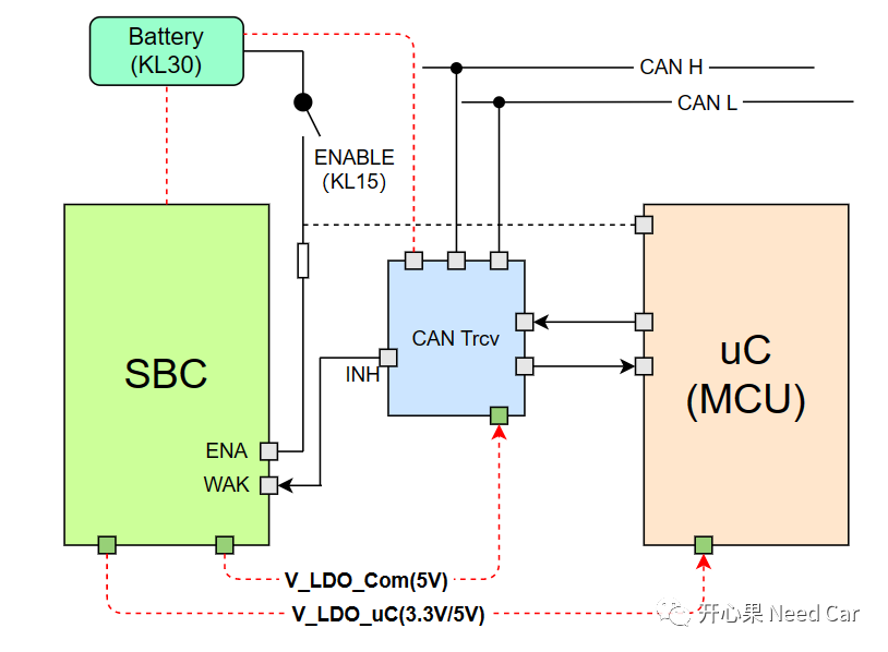
Regarding the wake-up conditions of the uC (MCU), we have discussed this before. You can refer to the previous article “Embedded Development: How to Understand ECU Wake-up, Sleep, and Reset?” The relationship between MCU power supply and the power management chip SBC (System Basic Chip) is illustrated as follows:
Generally speaking, the wake-up of a node (MCU) is controlled by two aspects: hard lines and network disturbances.
(1) Hard Line Wake-up of MCU
The so-called hard line can be understood as IO operations, for example: KL15 hard line. The ignition commonly referred to goes from off to on, which essentially corresponds to the closure of the KL15 IO, thereby enabling the 12V power from the battery (KL30) to power the SBC’s ENA Pin. After that, the SBC outputs operating voltage to the corresponding devices, e.g., Transceiver and uC.
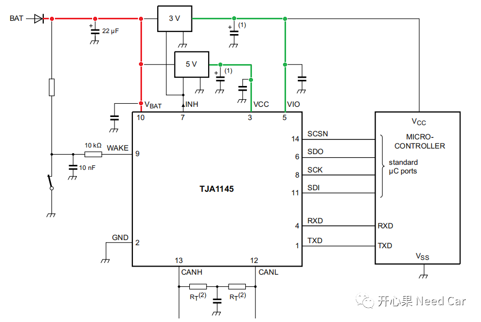
Note: The voltage output by the SBC to peripheral devices generally refers to the operating voltage required by these peripheral devices. Besides the normal operating voltage, there are also some monitoring voltages, e.g., CAN Trcv is often connected to KL30 (Battery) for monitoring its own voltage and bus disturbances. As illustrated in the figure below, VBAT is a constant power (12V), while the Vcc (5V) and Vio (3.3V) used by Trcv are provided by the SBC. That is to say: If Trcv detects a wake-up event (Wakeup Pattern or specified network management message) in Sleep mode, it pulls up the INH Pin, thereby enabling the SBC to output the operating voltage to Trcv.
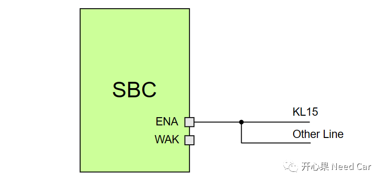
In the whole vehicle, some nodes are controlled by the KL15 hard line for wake-up, while others are not controlled by the KL15 hard line. If a node is controlled by the KL15 hardware, the KL15 hard line generally acts on the SBC, which controls whether the uC is powered, thus making it possible for the node to wake up. In other words: Different nodes have different numbers and methods of wake-up sources. Of course, some SBCs may be enabled not only by one KL15 hard line but also by other hard lines (Other Line). Regardless of how many external hard lines affect the SBC, generally speaking, these hard lines are in an OR relationship, that is: each hard line can independently enable the SBC, thereby providing operating voltage to the MCU, Trcv, and other devices, thus waking up the corresponding devices.
(2) Network Disturbance
When the Trcv receives a specific wake-up timing or specified message, it pulls up the INH Pin, thereby pulling up the WAK Pin of the SBC, enabling the SBC, and then the SBC outputs operating voltage to the MCU, Trcv, and other devices, thus waking up the MCU.
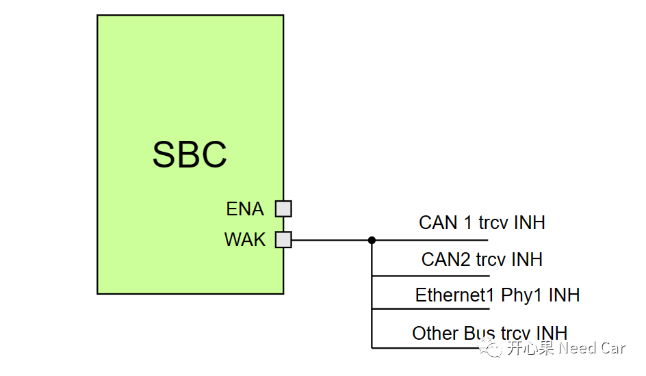
If a node uses multiple or several same-type Trcvs, the INH of each Trcv and the SBC WAK are in a parallel relationship. This means that any INH of the Trcv can enable the SBC, thereby waking up the MCU.
For the Lin bus, it may not be used as a wake-up source in engineering but is subordinate to the wake-up timing of CAN/Flexray/Ethernet.
Conditions for MCU Power Down
The power down process (Shutdown) of the MCU is different from the power-up process. When the MCU powers up, it can be woken up as long as one wake-up source is triggered. However, if the MCU wants to power down, it must check each wake-up source. The MCU can only execute the power down process when all wake-up sources no longer request communication.
-
All triggering wake-up hard line states, i.e., whether the KL15 and other hard lines are pulled low (Off state); -
Whether there are still diagnostic requests; -
Whether there are still network management messages; -
Whether there are still upper layer user communication requests, etc.
When all of the above requests are not met, the program begins to execute the MCU’s power down process. In the Autosar architecture, the above conditions are periodically checked by BswM, and the rules in BswM need to be designed by the developer. When the power down process is satisfied, BswM will notify EcuM, which controls the power down timing of the node.
Previous Highlights
Summary of previous excellent articles on Autosar: 151~200
Installation pitfalls of eProsima Fast DDS
Embedded Development: CMake-based development in VSCode
Bootloader Development: Why is SBL (Secondary Bootloader) needed?
Fast/Slow recovery mechanisms after Busoff
Open-source Fast-DDS installation example and DDS model architecture
DDS overview and DCPS model
Cross-compiling C and C++ based on CMake
TRACE32: Multi-core debugging configuration
Autosar EcuM: A brief analysis of APP from RUN to POST_RUN
Autosar Network Management: Discussing whether CAN FD frames can wake up the network?
Embedded Development: WWD of TLF35584 external watchdog
Embedded Development: How to understand ECU wake-up, sleep, and reset?
Basic C Language: The use of do{…}while(0), very elegant
Autosar EcuM: The startup and shutdown process of ECU
Embedded Development: Enabling Cached function leads to data consistency issues
Click below to follow, let’s discuss Autosar/Embedded Development together. If needed, contact the author to join the group for more professional answers.