Table of Contents
1. Introduction to Voltage Comparators
2. Working Principle of Voltage Comparators
3. Classification of Voltage Comparators
4. Single-Supply Comparators
1. Practical Single-Supply Comparator Built with LM393
2. Proteus Waveform Transformation Simulation Results
3. Proteus Simulation – Light-Controlled Relay Switching Circuit Based on Voltage Comparator
5. Hysteresis Comparators
1. Practical Hysteresis Comparator Built with LM358
2. Hysteresis Comparator Waveform Transformation Simulation Results
6. Window Comparators
1. Window Comparator Built with LM358
2. Proteus Simulation of Window Comparators
7. Conclusion
1. Introduction to Voltage Comparators
A voltage comparator is a circuit that distinguishes and compares input signals, serving as a fundamental unit in non-sinusoidal waveform generation circuits. It typically has two input terminals: the non-inverting input and the inverting input, along with one output terminal.
2. Working Principle of Voltage Comparators
The input signal is compared with a reference voltage, and based on the comparison result, a high or low output signal is generated. This characteristic allows voltage comparators to be used in various alarm circuits and automatic control switching circuits.
3. Classification of Voltage Comparators
Common types of voltage comparators include: single-supply comparators, hysteresis comparators, window comparators, and integrated voltage comparators.
4. Single-Supply Comparators
The circuit has only one threshold voltage. As the input voltage  gradually increases or decreases, when it crosses the threshold voltage
  , the output voltage
  will switch from high to low, or from
  to
to  .
.
1. Practical Single-Supply Comparator Built with LM393
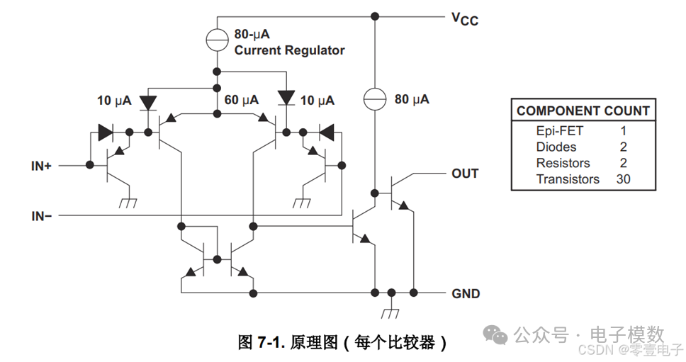
Figure 7-1 is the schematic provided in the LM393 datasheet, showing that it uses an open-collector output configuration.
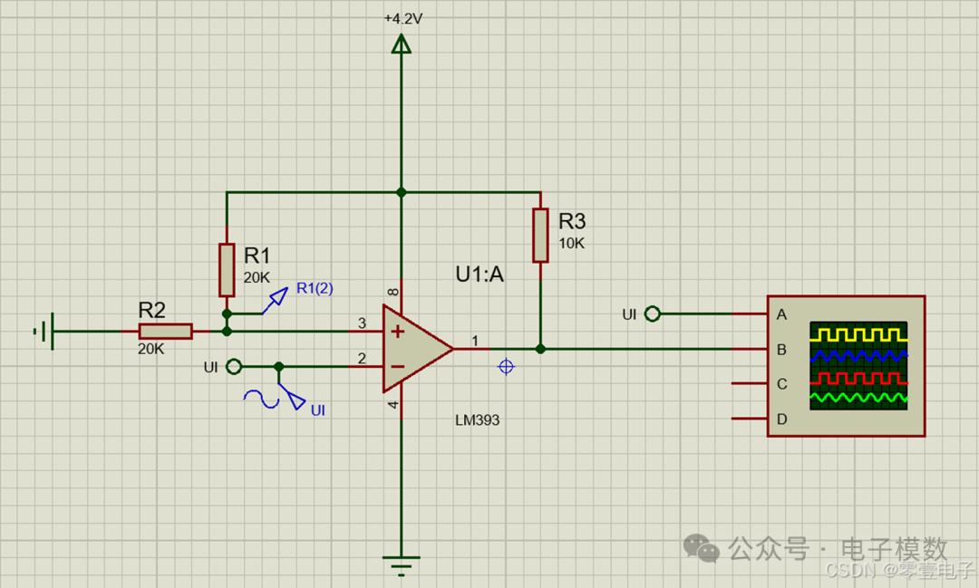
In the diagram below, the inverting input is the input voltage  , while the non-inverting input serves as the threshold voltage
  . The threshold voltage is obtained through a voltage divider formed by
  and
and  .
.

 is a pull-up resistor, ensuring that the output high level is 4.2V. Since the comparator uses an open-collector output configuration, the output high level has almost no load capacity.
2. Proteus Waveform Transformation Simulation Results
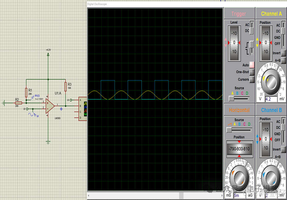
The input is a 50Hz signal with an amplitude of 2V and an offset of 2V; the simulation results are shown below. It can be seen that when  is greater than 2V,
  is 0V. When
  is less than or equal to 2V,
  is 4.2V. Clearly, this circuit transforms the input sine wave into a square wave signal with the same period.
3. Proteus Simulation – Light-Controlled Relay Switching Circuit Based on Voltage Comparator
This circuit validates a practical light-controlled circuit. By replacing the inverting input with a regular resistor and a light-dependent resistor (LDR), it can become a light-controlled circuit. When there is light and the light intensity is above a certain value, the voltage divider formed by LDR1 and R4 is less than the threshold voltage, and the relay remains in a normally open state.
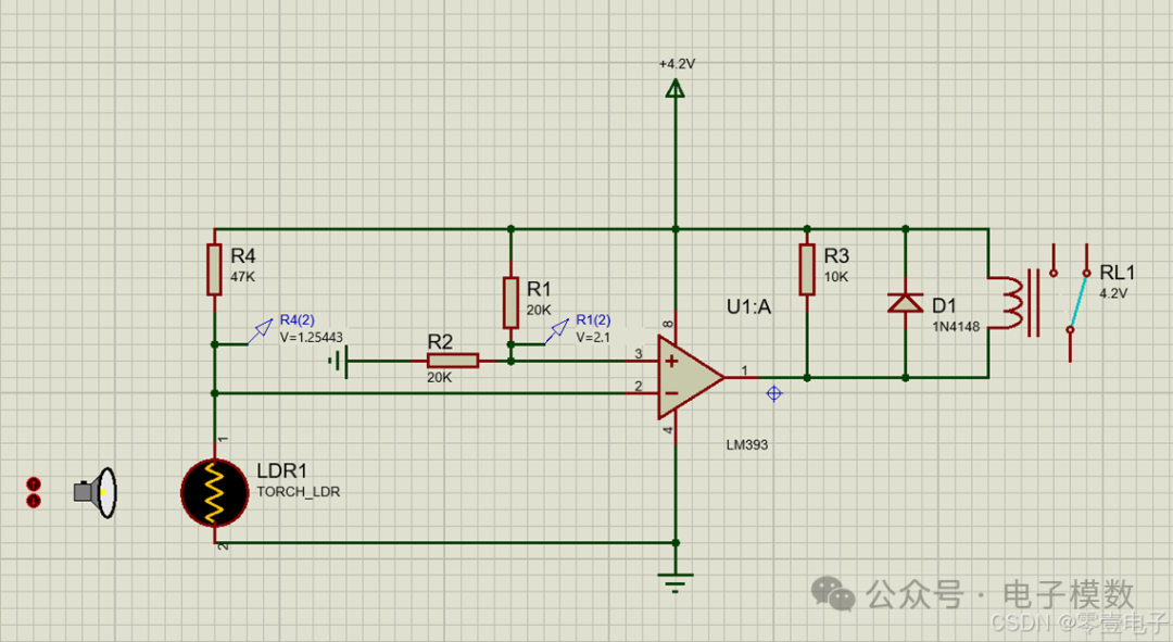 When there is no light or the light intensity is weak, the voltage divider formed by LDR1 and R4 exceeds the threshold voltage, causing the relay to engage, which can be used to control other circuits.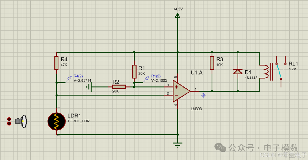
5. Hysteresis Comparators
Single-supply comparators have only one threshold voltage  , so any small change in the input voltage
  near
near  can cause a jump in the output voltage
  . This characteristic makes it very sensitive but less resistant to interference. The hysteresis feature of hysteresis comparators can enhance their resistance to interference.
1. Practical Hysteresis Comparator Built with LM358
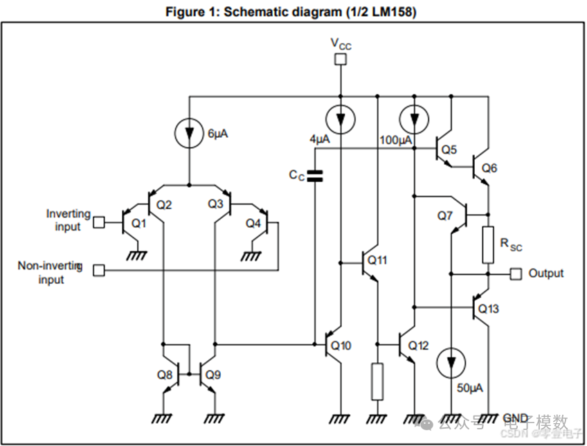
Figure 1 is the schematic provided in the datasheet, with a maximum output voltage swing range of 0 V to (+VCC – 1.5 V).
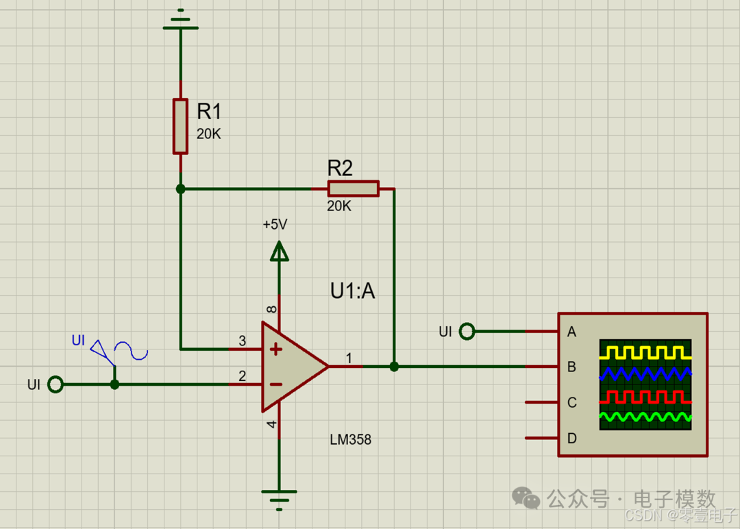
The following diagram shows the hysteresis comparator circuit simulated using LM358. From the datasheet, the maximum output of LM358 is +VCC-1.5V. It can be calculated that  should be +5-1.5=3.5V, but the simulation actually yields a maximum output of about 4V. First, the threshold voltage
  is calculated based on the circuit principles.
 ①
①
 ②
②
 ③
③
From the above three equations, it can be seen that when the threshold voltage  is
is

where  high level is 4V and low level is 0V. Therefore,
  ,
,  .
.
2. Hysteresis Comparator Waveform Transformation Simulation Results
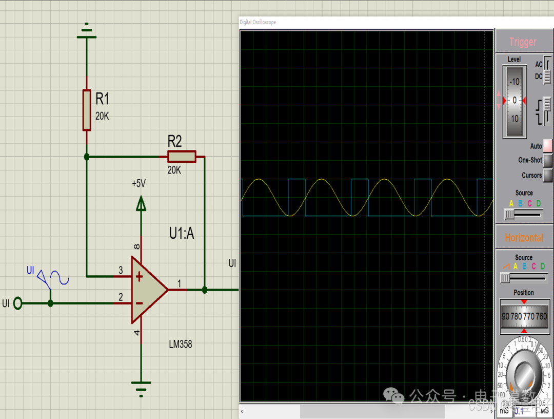
The input is a 50Hz signal with an amplitude of 2V and an offset of 2V. When  slowly decreases from +4V to 0V,
  switches from 0V to 4V; when
  slowly increases from 0V to 2V,
  switches from 4V to 0V. The waveforms clearly show that both processes exhibit hysteresis functionality. During the decrease of
  , the output level only flips when close to
  ; during the increase of
  , the output level only flips when close to
  . The input voltage increase and decrease processes need to pass through
  for the output level to flip, enhancing the resistance to interference compared to single-supply comparators.
6. Window Comparators
1. Window Comparator Built with LM358
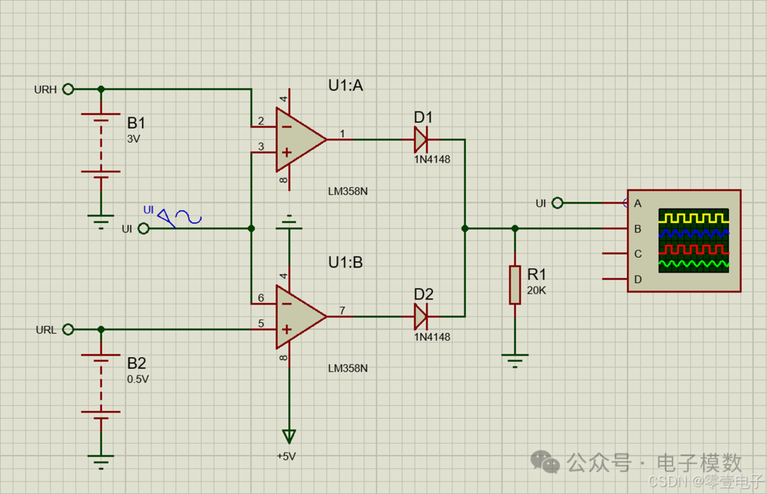
Taking the following diagram as an example, when the input voltage  is between two reference voltages
  and
and  , the output voltage is low; otherwise, it is high.
2. Proteus Simulation of Window Comparators
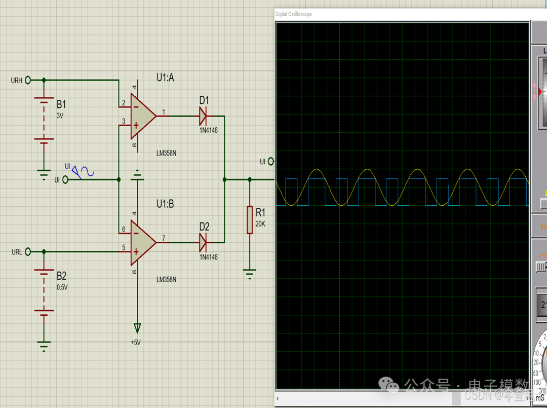
From the simulation waveform, it can be seen that when  is high, the output voltage
  is high; conversely, the output voltage
  is low. Window comparators can be used in simple voltage detection circuits to determine if the voltage is within a certain range. If multiple circuits are used, they can also serve as battery level indicator circuits.
7. Conclusion
As an electronics hobbyist, I have been trying to learn both software and hardware knowledge for a long time and have documented what I have learned and thought for everyone’s reference. Creating this content is not easy, and I hope readers can provide suggestions or requests, and please point out any issues for discussion.