From Mechanical Strain to Energy Conversion
The world of sensing technology is vast and boundless. The previous article laid a solid foundation based on changes in electrical parameters. Here, physical laws are applied in a more direct and sometimes more ingenious way: the elastic deformation of solids, the dynamic characteristics of fluids, the transfer and conversion of heat, and even the marvelous interactions between magnetic fields and sound waves all become tools for us to perceive the world. Understanding these principles means we can tackle various challenges, from macro force measurement to micro flow monitoring, from extreme environment detection to precise position feedback. This article will serve as your in-depth guide through this jungle of intelligent technology.
Part One: Mechanical Response and Elastic Deformation
This is the most intuitive type of sensing principle: an object deforms under external forces, and by measuring this deformation, we can determine the magnitude of the external force. These sensors directly convert changes in mechanical quantities into mechanical displacements, which are then measured through mechanical amplification or electrical methods.
Bourdon Tube: The Classic and Timeless Pressure Measurement
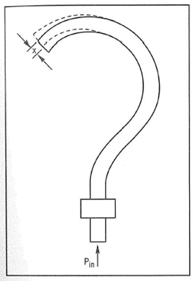
- Physical Image and Principle: A flat hollow tube bent into aC shape, spiral shape, or helical shape, one end fixed and connected to a pressure source, while the other end is sealed and can move freely. When pressure is applied inside the tube, its non-circular cross-section (usually elliptical or flattened) tends to become circular, and this “expansion“ effect causes the entire bent tube to straighten, resulting in a noticeable displacement at the free end. This displacement drives a pointer to rotate on the dial through a linkage amplification mechanism.
- In-depth Analysis:
- The Mystery of Cross-Section Shape: The reason for using a flattened or elliptical cross-section is that it has a much greater strain tendency to become circular under internal pressure, thus amplifying small pressure changes into more significant end displacements, improving sensitivity.
- Material Selection: Materials with excellent elasticity must be used, such as phosphor bronze, beryllium copper alloy, or stainless steel, to ensure complete recovery to the original state after pressure removal, avoiding permanent plastic deformation.
- Accuracy and Linearity:The relationship between the displacement of the C-shaped tube and pressure exhibits certain non-linearity, especially in high-pressure ranges. Using spiral or helical designs can increase the total displacement at the free end, improving linearity and measurement accuracy.
- For example: The “Guardian of Industrial Safety“——Pressure Gauge is the most ubiquitous device in any chemical plant, boiler room, or hydraulic station. It requires no power supply, has a robust structure, and provides intuitive readings, making it the first and most reliable line of defense for equipment operators and maintenance engineers to assess system status. For instance, in a steam boiler, operators ensure the boiler operates within a safe pressure range by observing the pointer position of the Bourdon tube pressure gauge, preventing overpressure explosion accidents. Its mechanical nature provides high reliability and anti-interference capability, which is difficult for any electronic sensor to completely replace in the field of basic safety monitoring. In extreme environments such as the containment of nuclear power plants, specially designed Bourdon tube pressure gauges remain critical monitoring devices due to their inherent safety and reliability.
Part Two: Bellows and Diaphragms: Sensitive Pressure Sensing Elements
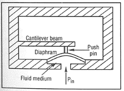
- Principle:Bellows are cylindrical thin-walled metal tubes composed of a series of corrugations, whilediaphragms are taut circular thin metal or non-metal membranes. They are more sensitive than Bourdon tubes under pressure, capable of producing greater displacements or strains. The axial displacement of the bellows is essentially linearly related to pressure, while the central displacement of the diaphragm depends on its shape and clamping method.
- Combining with Electrical Signals: These mechanical elements output displacements. To convert them into electrical signals, designers cleverly combine them with the principles learned in Chapter 11:
- Strain Gauge Scheme: Strain gauges are attached to the back of the diaphragm or specially designed elastic beams (such as cantilever beams). Pressure deforms the diaphragm, causing the elastic beam to bend, and the strain gauge detects its strain and converts it into a change in resistance. This scheme is cost-effective but produces a small output signal, requiring fine signal conditioning.
- LVDT Scheme: The central displacement of the bellows or diaphragm is transmitted to the core of the LVDT through a push rod, converting pressure displacement into a linear voltage signal. This scheme has high accuracy and good linearity but is relatively expensive.
- Capacitive Scheme: The diaphragm itself acts as one capacitor plate, with another fixed plate parallel to it. Pressure deforms the diaphragm, changing the distance between the two plates, thus altering the capacitance. This scheme has extremely high sensitivity and good dynamic response, making it the preferred choice for high-performance pressure sensors.
Part Three: Measurement of Force and Torque: Specialized Techniques for Force and Torque Measurement
- Load Cell: Load Cell:
- Principle: Typically based on the strain gauge principle. A carefully designed elastic body (such as cylindrical, beam-type, or wheel spoke type) will produce a strain proportional to the external force at specific locations when subjected to external force. Strain gauges (usually in a full bridge configuration) are attached to these locations to measure the magnitude of the force. The design of the elastic body is crucial; it needs to concentrate the external force to the strain gauge attachment points and minimize the effects of lateral forces and bending moments.
- For example: Rocket Engine Test Stand When testing the enormous thrust of a rocket engine, the engine is fixed to a massive cylindrical load cell. When the engine ignites, producing hundreds of tons of thrust, this immense force causes the elastic body made of high-strength alloy steel to undergo extremely small compressive deformation (possibly only a few tens of microstrains). The precision strain gauge full bridge attached detects this deformation, outputting a weak millivolt signal, which is amplified and calibrated to accurately read the engine’s real-time thrust. This is a typical application in the aerospace industry that requires high precision and reliability. The entire test stand may be supported by multiple load cells, summing to obtain the total thrust, ensuring measurement accuracy and reliability.
- Torque Sensor: Torque Transducer/Torque Shaft:
- Principle: When a shaft transmits torque, shear deformation occurs, producing principal stresses at a 45-degree angle to the axis (one tensile stress and one compressive stress).
- Strain Gauge Method: Four strain gauges are attached at 45-degree angles on the shaft, with two sensing tensile strain and two sensing compressive strain, forming a full bridge circuit to directly measure the shear strain caused by torque. The challenge of this method lies in how to reliably transmit the signal from the rotating shaft to the stationary display instrument, typically using slip rings or wireless telemetry technology.
- Phase Difference Method: Two identical gears and electromagnetic sensors are installed at both ends of the shaft. When the shaft transmits torque, torsional deformation occurs, causing a slight relative angular displacement between the two gears. This displacement manifests as a phase difference in the output signals of the two sensors. The magnitude of the phase difference is proportional to the torque. This method is non-contact and highly reliable, but its accuracy is usually lower than that of the strain gauge method.
- For example: Power Monitoring of Ship Propulsion Shaft System A phase difference torque sensor is installed on the drive shaft of large cargo ships or cruise ships. By monitoring the torque and speed on the drive shaft in real-time, the power output from the engine to the propeller can be accurately calculated. This is crucial for optimizing engine performance, improving fuel economy, and timely detecting transmission system faults (such as bearing wear and shaft misalignment). The non-contact measurement method makes it very suitable for high-speed, high-power rotating machinery. By continuously monitoring torque and power data, shipping companies can develop optimal speed strategies, significantly reducing fuel costs.
Part Two: Thermal Expansion and Thermoelectric Effects——Driving and Creating Temperature Differences
The volume change of substances due to temperature changes is a universal and powerful physical effect, cleverly utilized for temperature measurement and control.
Thermal Expansion: A Universal Phenomenon in Solids, Liquids, and Gases
- Bimetallic Strip:
- Principle: Two metal strips with different thermal expansion coefficients are rolled together. When the temperature changes, the metal layer with the larger expansion coefficient (active layer) elongates more, forcing the entire element to bend towards the side of the metal layer with the smaller expansion coefficient (passive layer). The curvature of the bend is proportional to the temperature difference.
- For example: Thermostat in Household Appliances“Thermostat“ In old electric irons, electric kettles, or air conditioning overload protectors, the bimetallic strip is the core control element. When the temperature reaches the set value, the bending of the bimetallic strip is sufficient to trigger a mechanical switch, cutting off the circuit. When the temperature drops, it returns to its original state, reconnecting the circuit. This device has a simple structure, low cost, and reliable operation, playing the role of a safety guard in countless household appliances. In the industrial field, bimetallic thermometers are also commonly used for on-site display, especially in high-vibration situations, where their mechanical structure is more durable than glass thermometers.
- Liquid Expansion:
- Principle: Utilizing the thermal expansion and contraction of liquids (such as mercury or alcohol) in a sealed capillary tube to indicate temperature. The volume expansion coefficient of the liquid is much greater than that of glass, so the rise and fall of the liquid column can clearly show temperature changes.
- For example: High-Precision Glass Thermometer In laboratories or situations requiring on-site calibration, the mercury glass thermometer is still regarded as one of the benchmark instruments due to its high precision and stability. Although its output cannot be directly electronic and there is a risk of mercury contamination (which is gradually being replaced by organic liquids such as alcohol and galinstan), it remains a trusted standard in certain demanding calibration fields. For example, in the validation of sterilization pots in the pharmaceutical industry, the highest precision glass thermometers are required to confirm that the process temperature meets regulatory requirements.
- Gas Expansion (Gas Thermometer):
- Principle: A temperature bulb filled with inert gas (such as nitrogen) is connected to a pressure sensor through a capillary tube. According to the ideal gas law PV = nRT, the volume V is fixed, and as the temperature T increases, the pressure P must increase.
- For example: Wide-Area Temperature Measurement When measuring the average temperature of an area or the surface temperature of an object without direct contact, the gas thermometer shows its advantages. A larger temperature bulb can reflect the average temperature of the space it occupies. By using capillary tubes of different lengths, long-distance measurements can be achieved. This system is applied in temperature monitoring of large warehouses and agricultural greenhouses. Its advantage is that the entire system has no electrical components at the measurement point, making it intrinsically safe and suitable for environments with explosion risks.
Thermoelectric Effect: Peltier Effect——The Magic of Refrigeration
- Principle: When direct current passes through a thermocouple made of two different semiconductor materials (P-type and N-type), heat absorption or release occurs at the junction of the thermocouple. The direction of the current determines whether it absorbs heat (refrigeration) or releases heat (heating). This is essentially the reverse effect of the Seebeck effect. The cooling capacity of a single thermocouple is very small, so in practical applications, dozens or even hundreds of thermocouples are connected in series to form a Peltier module.
- For example: Portable Semiconductor Refrigerator and Electronic Chip Cooling
- Portable Semiconductor Refrigerator: Can be used in vehicles, capable of both cooling and heating by switching the direction of current. It has no moving parts, making it quiet and reliable.
- PCR Instrument (Polymerase Chain Reaction): In biological laboratories, PCR technology requires samples to undergo rapid and precise cycling between high temperatures (~95°C), low temperatures (~50°C), and moderate temperatures (~72°C). The Peltier module, due to its ability to heat and cool quickly and its high temperature control accuracy, has become the core temperature control element of modern real-time fluorescence quantitative PCR instruments. Its precise temperature control is key to ensuring the efficiency and specificity of DNA amplification.
- High-End CPU/GPU Cooling: In some situations where noise and reliability are of utmost importance, Peltier coolers are used to assist in cooling chips. They can lower the cold side temperature far below the ambient temperature, providing a greater heat dissipation temperature difference. However, care must be taken to prevent condensation and manage the large amount of heat generated on the hot side.