Click the above“blue text” to follow us Torque Sensor Calibration Methods
 1.Overview
Torque is a traditional and important parameter in force measurement, widely used in industries such as automotive, shipbuilding, aerospace, and power generation. In these industries, precise measurement and control of torque values are crucial, especially in product research, testing analysis, quality inspection, and safety control. Accurate and reliable torque measurements can significantly enhance product quality.
To ensure the accuracy of measurement data, torque sensors should be calibrated in a timely manner.
 2.Torque Sensor Calibration Methods
The static calibration methods for torque sensors mainly include: lever weight method, static weight torque standard machine, and reference torque standard machine.
1, Lever Weight Method
1.1Principle
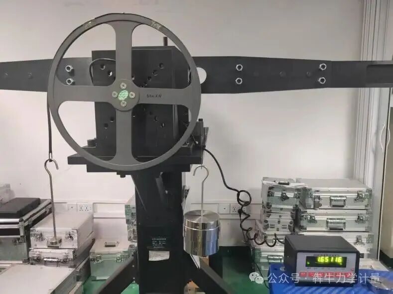
This is the simplest and most common calibration method, based on Newton’s second law (F=ma), which generates standard torque through force and lever arm.
A lever arm of known mass and precise length is mounted on the axis of the torque sensor, with a known mass standard weight suspended at the end of the lever arm.
The acceleration due to gravity (g) is known, thus the standard torque value T = Force (F) × Lever Arm (L) = m × g × L.
1.2Advantages and Disadvantages
Advantages: Simple operation, low cost, small range force lever can be used for on-site calibration.
Disadvantages: Manual loading of weights is labor-intensive, and the loading torque range is limited by the weight and lever arm length.
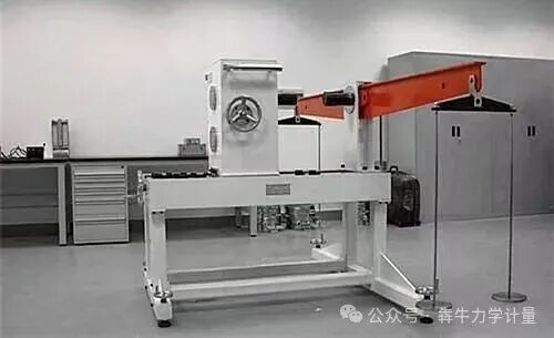
2, Static Weight Torque Standard Machine
2.1Principle
The torque standard machine uses a static weight structure, reproducing torque values based on the gravitational force of the weights and the buoyant force of the air acting on the weights, multiplied by the length of the lever arm.
The static weight torque standard machine mainly consists of a balancing force device, balancing lever arm, workbench, main knife edge, standard lever arm, and base. The standard lever arm and weights combine to produce a standard torque value, which is transmitted to the torque sensor being tested.
2.2Advantages and Disadvantages
Advantages: High accuracy level; high degree of automation; wide loading range; automatic data collection and processing.
Disadvantages: High equipment and maintenance costs.
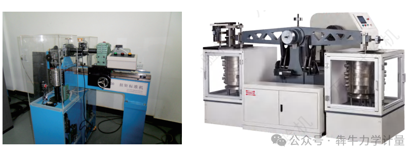
3, Reference Torque Standard Machine
3.1 Principle
The torque sensor to be calibrated is connected in series with a “standard torque sensor” on the standard torque machine. During calibration, the standard torque machine applies a torque, which is measured by a high-precision “reference sensor” (standard sensor) inside the torque machine, while simultaneously reading the output value of the sensor being calibrated. By comparing the readings of the two sensors, calibration can be completed.
3.2Advantages and Disadvantages
Advantages: Simple equipment structure; torque sensors can be connected in parallel or series. The range and accuracy are determined by the reference sensor.
Disadvantages: Accuracy is generally lower than that of static weight torque standard machines due to installation and connection influences.
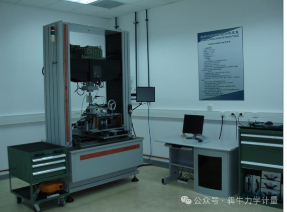
 3.Considerations for Lever Weight Method Calibration
1, Ensure the force arm and weight force act vertically
The torque sensor will experience a twisting angle when subjected to torque from the lever arm and weight force. This disrupts the horizontal state of the lever arm, shortening it and causing the applied torque value to be less than the nominal value, leading to negative deviations in the calibration results.
To ensure the lever is horizontal, the installation angle of the torque sensor must be adjusted in a timely manner. The standard lever should be equipped with a high-sensitivity level bubble for easy observation of the lever’s horizontal state.
2, Use a secure joint
If there is a gap in the connection between the joint and the torque sensor and lever, it can cause deflection and shear deformation due to the radial force and bending moment from the weight force and lever, resulting in significant errors in the applied torque value and increasing the variability of the torque value, thus reducing the reliability of the measurement results.
The joint connecting the torque sensor and lever arm should have sufficient stiffness, and the lever and sensor should be tightly connected without radial gaps.
3, Choose the standard lever appropriately
The lever arm length should be selected based on the measurement range of the torque sensor.
While ensuring the stiffness of the lever, the weight of the standard lever should be minimized, using lightweight alloy materials (such as aluminum alloy) to ensure that the self-weight of the standard lever does not affect the readings of small-range torque meters.
 4.General Steps for Calibration (Using Standard Torque Machine Method as an Example)
1. Preparation
Inspect the appearance of the sensor, confirming its model, range, and other basic information. Clean the installation surface.
2. Installation
Securely install the torque sensor on the standard torque machine, ensuring good coaxiality to avoid introducing additional bending moments or axial forces.
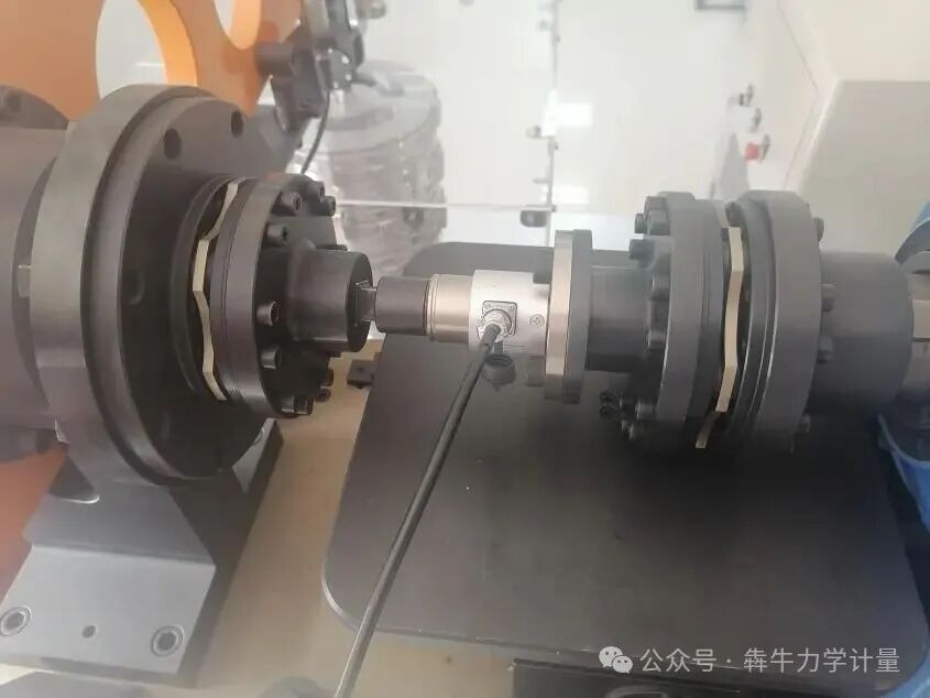
3. Connection
Connect the power supply and output signal lines of the sensor to the reading instrument (or data acquisition system). Power on and preheat for a period (e.g., 30 minutes) to stabilize its performance.
4. Preloading
Perform 2-3 full-scale load and unload cycles on the sensor to eliminate internal stresses in the mechanical structure and ensure repeatability.
5. Calibration Point Selection
Based on the range and accuracy requirements, typically select at least 5-8 points (e.g., 0%, 20%, 40%, 60%, 80%, 100% of full scale).
6. Official Loading
Starting from zero, gradually load to the selected calibration points.
At each point, after stabilization, record both the standard value displayed by the standard torque machine and the output value of the sensor being tested (which can be voltage, current, or frequency values).
After loading to full scale, unload gradually, similarly recording data at each point.
Typically, 3 cycles of repeatable loading and unloading are required.
7. Reverse (Counterclockwise) Calibration
After completing calibration in one direction (e.g., clockwise), perform reverse (counterclockwise) calibration following the same steps.
8. Data Processing
Calculate the average of the 3 readings at each calibration point.
Based on the recorded data, calculate key indicators such as sensor sensitivity, non-linearity error, hysteresis error, and repeatability error.
9. Generate Report
Generate a calibration curve or calibration certificate based on the calculation results, providing conclusions on the metrological performance of the sensor.
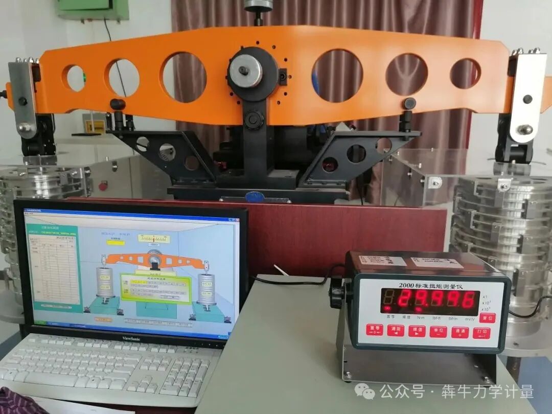
 5.Calibration Considerations
1. Traceability Chain
The core of calibration is traceability. The standard instruments used (weights, standard torque machines) must themselves be calibrated by higher-level metrology institutions and possess valid calibration certificates to ensure that the measurement values can be traced back to national or international standards.
2. Environmental Conditions
Environmental factors such as temperature and humidity can affect calibration results, so it should be conducted in a well-controlled laboratory.
3. Installation Errors
Incorrect installation (eccentricity, bending) is one of the main sources of error.
4. Calibration Cycle
Torque sensors should be calibrated regularly, typically once a year, or the cycle should be shortened based on usage frequency and severity of working conditions.
 6.Conclusion
 With the rapid development of industry and intelligence, the demand for torque measurement and calibration technology is becoming increasingly urgent. Static weight torque standards, as the main force in torque standard transmission, have begun to be recognized in the metrology field. With the advancement of the national industrial 2025 initiative and intelligent work, the prospects for torque measurement are broad, and new torque standards are bound to emerge in large numbers, providing measurement means for the quality and reliability of various products.
 ENDClick “View” and “Share” to spread knowledge and positive energy

 Benniu Mechanics Measurement
Scan to follow and share more measurement knowledge.
Your likes, follows, and shares are my greatest motivation for continuous sharing!
Welcome to comment and discuss measurement pain points.
Please open in the WeChat client
PreviousHighlights
Quick look! The intelligent lead seal management system leaves no corner for cheating at gas stations
Explosive! The fuel dispenser anti-cheating system becomes the “guardian” of taxes and consumers
Shocking! “Ghost scales” rampant in the market, a mysterious nemesis emerges!
Explosive! The weighing inspection undergoes a major transformation, saying goodbye to the nightmare of weight handling!
Shocking revelation: How strong is China’s “big country heavy weapon” in the field of mechanics?
The impact of cement bending and compressive fixtures on force values and calibration
New regulations for inspection and testing are here! Individuals must also take responsibility!