
Practical Guide: PLC Memory Planning Methods for Clearer Program Structure!
1.
1. Scenario Restoration
In a large automation production line project, we encountered the problem of chaotic PLC program structure that was difficult to maintain.
The system includes multiple workstations, each with independent control logic, but all data and programs were disorganized.
This led to difficulties in understanding and debugging the program, and frequent data conflicts.
We realized that reasonable memory planning is crucial for enhancing the program’s readability, maintainability, and operational efficiency.
2.
2. Principle Analysis
The core principle of PLC memory planning is to modularize data and programs and allocate memory resources rationally. This mainly includes the following aspects:
1. Data Block (DB) Planning: Classifying and storing data according to function, such as workstation parameter DB, system status DB, etc. 2. Function Block (FB) Design: Encapsulating reusable functions into FBs to enhance code reusability. 3. Function (FC) Planning: Encapsulating independent functional logic into FCs, such as alarm handling and data logging. 4. Variable Naming Standards: Using a unified naming convention to improve code readability. 5. Comment Standards: Providing detailed comments on each program block’s function and parameter description.
3.
3. Code Implementation

3.1 PLC Program Design Description
Taking Siemens S7-1200 PLC as an example, we will organize the program according to the following structure:
OB1: Main Program Cycle FB1-FB10: Control Logic for Each Workstation FC1: System Initialization FC2: Alarm Handling FC3: Data Logging DB1: System Parameters DB2-DB11: Parameters for Each Workstation DB12: System Status
3.2 IO Example
Address|Symbol|Data Type|Comment —|—|—|— I0.0|Start_Button|BOOL|Start Button I0.1|Stop_Button|BOOL|Stop Button I0.2|Emergency_Stop|BOOL|Emergency Stop Q0.0|System_Running|BOOL|System Running Indicator Q0.1|Alarm_Light|BOOL|Alarm Indicator
3.3 PLC Ladder Diagram Example
The following is a partial ladder diagram example of the OB1 main program cycle:
|Start_ButtonStop_ButtonEmergency_StopSystem_Running +—-][———-][————]/[——————–()————- | |FC1(System Initialization) +—-CALL———— | |FB1(Control for Workstation 1) +—-CALL———— |IN1:= “DB2”.Param1 |IN2:= “DB2”.Param2 |OUT:= “DB12”.Station1_Status | |FB2(Control for Workstation 2) +—-CALL———— |IN1:= “DB3”.Param1 |IN2:= “DB3”.Param2 |OUT:= “DB12”.Station2_Status | |FC2(Alarm Handling) +—-CALL———— | |FC3(Data Logging) +—-CALL————
4.
4. Application Case
Let’s take a simplified automation production line as an example to implement workstation control and data management.
4.1 System Parameter DB (DB1)
DATA_BLOCK “SystemParams” {S7_Optimized_Access:=’TRUE’} VERSION: 0.1 STRUCT CycleTime: Time:=T#100MS; MaxStations: Int:=10; AlarmDelay: Time:=T#5S; END_STRUCT; BEGIN END_DATA_BLOCK
4.2 Workstation Parameter DB (DB2)
DATA_BLOCK “Station1Params” {S7_Optimized_Access:=’TRUE’} VERSION: 0.1 STRUCT SetpointTemp: Real:=80.0; MaxPressure: Real:=10.0; ProcessTime: Time:=T#30S; END_STRUCT; BEGIN END_DATA_BLOCK

4.3 Workstation Control FB (FB1)
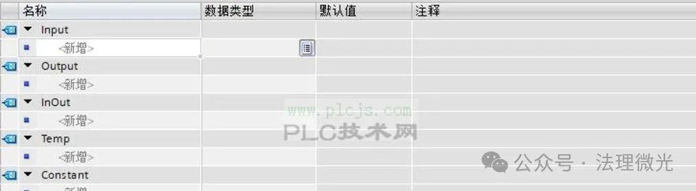
FUNCTION_BLOCK “StationControl” {S7_Optimized_Access:=’TRUE’} VERSION: 0.1 VAR_INPUT Start: Bool; Stop: Bool; SetpointTemp: Real; MaxPressure: Real; ProcessTime: Time; END_VAR VAR_OUTPUT StationStatus: Int; AlarmCode: Int; END_VAR VAR Timer: TON; CurrentTemp: Real; CurrentPressure: Real; END_VAR
BEGIN // Workstation control logic IF #Start THEN
Timer(IN:=TRUE, PT:=#ProcessTime);
IF #Timer.Q THEN
StationStatus:=2; // Completed
ELSIF #CurrentTemp > #SetpointTemp OR #CurrentPressure > #MaxPressure THEN
StationStatus:=3; // Alarm
AlarmCode:=1; // Temperature or pressure exceeded
ELSE
StationStatus:=1; // Running
END_IF; ELSIF #Stop THEN
StationStatus:=0; // Stopped
Timer(IN:=FALSE);
END_IF; END_FUNCTION_BLOCK
4.4 Alarm Handling FC (FC2)
FUNCTION “AlarmHandler”: Void {S7_Optimized_Access:=’TRUE’} VERSION: 0.1 VAR_INPUT AlarmCode: Int; END_VAR VAR_OUTPUT AlarmLight: Bool; AlarmMessage: String; END_VAR
BEGIN CASE #AlarmCode OF 1:
AlarmLight:=TRUE;
AlarmMessage:=’Temperature or Pressure Exceeded’;
2:
AlarmLight:=TRUE;
AlarmMessage:=’Process Timeout’;
ELSE
AlarmLight:=FALSE;
AlarmMessage:=”;
END_CASE; END_FUNCTION
4.5 Main Program OB (OB1)
ORGANIZATION_BLOCK “Main” {S7_Optimized_Access:=’TRUE’} VERSION: 0.1
BEGIN // System Initialization “SystemInit”();
// Workstation 1 Control “StationControl”(Start:= “Start_Button”, Stop:= “Stop_Button”, SetpointTemp:= “Station1Params”.SetpointTemp, MaxPressure:= “Station1Params”.MaxPressure, ProcessTime:= “Station1Params”.ProcessTime, StationStatus=> “SystemStatus”.Station1_Status, AlarmCode=> #TempAlarmCode);
// Alarm Handling “AlarmHandler”(AlarmCode:= #TempAlarmCode, AlarmLight=> “Alarm_Light”, AlarmMessage=> “SystemStatus”.AlarmMessage);
// Data Logging “DataLogging”(); END_ORGANIZATION_BLOCK
5.
5. Conclusion
Through reasonable PLC memory planning, we successfully transformed the originally chaotic program structure into a modular and maintainable system. The main improvements include:
1. Data Classification Storage: Using dedicated DBs to store system parameters and workstation parameters improved data management clarity. 2. Functional Modularization: Encapsulating workstation control logic into FBs and general functions such as alarm handling and data logging into FCs significantly enhanced code reusability and maintainability. 3. Naming Standardization: Adopting a unified naming convention, such as SystemParams, Station1Params, etc., made the program structure clear at a glance. 4. Comprehensive Comments: Adding detailed comments for each program block facilitated understanding and maintenance by other engineers.
This structured memory planning method not only improved the program’s readability and maintainability but also significantly reduced debugging time and system failure rates.
In future projects, we will continue to optimize this method to address more complex automation control requirements.