First, I would like to thank QQ group member Old Yang for selflessly guiding me.
Because I was not satisfied with the key layout available on the market, and I enjoy the creative process, I had the idea of making one myself. If the layouts on the market are suitable, I personally recommend buying a kit directly. If you want to understand the general process, you can take a look at: the world’s first programmable wireless 40% mechanical keyboard.
1. Positioning Plate and Shell
1. Layout Keys
First, use the KLE website to create your desired layout (it is recommended to log in with GitHub for easy saving of layouts). The website is quite simple to operate; first, select a preset that is relatively close, so it can be modified quickly.
Operation tips:
-
Modify key width by selecting the corresponding key, then enter the width in the
Propertiesbox below. -
Add keys: simply click
Add Key. -
Delete keys: select the corresponding key and click
Delete Keys. -
Move keys: select the corresponding key and modify
PropertiesforXandY. -
Modify key names: change the
Top LegendinProperties.
Continue modifying until you reach a suitable key position. It is best to check the position of your thumbs while typing; use the positions of the VBN keys as a reference. Of course, consider the difficulty of purchasing keycaps of various widths.
This is my layout (in Raw data), I don’t need a satellite axis, which means CAD is not necessary, but I need 4 of 1.25x, 4 of 1.75x, and the keycaps are hard to gather, so I eventually gave up.
[{c:"#c13828"},"Esc",{c:"#cccccc"},"Q","W","E","R","T","Y","U","I","O","P",{c:"#96938e"},"Back<br>Space"],
[{w:1.25},"Tab",{c:"#cccccc"},"A","S","D","F","G","H","J","K","L",{c:"#96938e",w:1.75},"Enter"],
[{w:1.75},"Shift",{c:"#cccccc"},"Z","X","C","V","B","N","M",{w:1.25},"<\n.",{c:"#c13828"},"Up",{c:"#96938e"},"Del"],
["Ctrl","Super","App",{w:1.25},"Alt",{c:"#f67f00",w:1.75},"Fn",{w:1.75},"Space",{c:"#96938e",w:1.25},"Fn1",{c:"#c13828"},"Left","Down","Right"]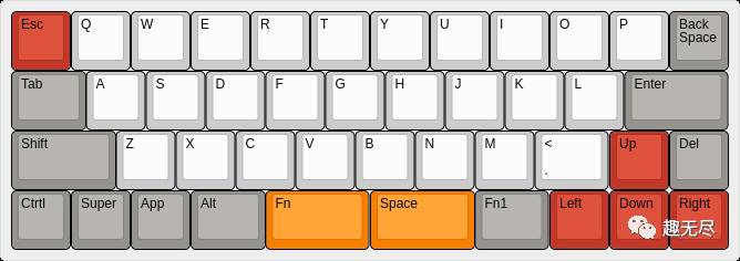
The one below requires a satellite axis; the drawing needs to be modified, but only requires 2 of 1.25x, 2 of 1.75x, and 2 of 2x.
[{c:"#c13828"},"Esc",{c:"#cccccc"},"Q","W","E","R","T","Y","U","I","O","P",{c:"#96938e"},"Back<br>Space"],
[{w:1.25},"Tab",{c:"#cccccc"},"A","S","D","F","G","H","J","K","L",{c:"#96938e",w:1.75},"Enter"],
[{w:1.75},"Shift",{c:"#cccccc"},"Z","X","C","V","B","N","M",{w:1.25},",",{c:"#c13828"},"Up",{c:"#96938e"},"Del"],
["CTRL","Super","App","Alt",{c:"#f67f00",w:2},"Fn",{w:2},"Space",{c:"#96938e"},"Fn3",{c:"#c13828"},"Left","Down","Right"]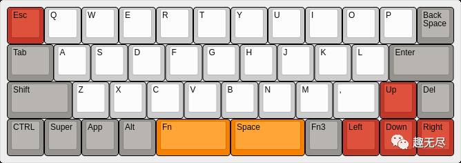
2. Generate Positioning Plate or Shell
-
Open http://builder.swillkb.com/, paste the ‘Raw data’ content from the previous step into
Plate Layout, leave other settings as default, and clickDraw MY CADto preview. By default, you will get an aluminum positioning plate, which you can print in CAD software and modify as needed (if you need a satellite axis, please read below). -
This website supports directly producing sandwich-style shell kits. In
Case Type, selectSandwich, and then preview (since this tool is very convenient, it is recommended to modify and preview simultaneously). -
Add a USB port by selecting
USB CutouttoON. ForLocation, enter a number; 0 is the center, negative numbers move left, and positive numbers move right. This option only supports USB output at the top of the keyboard; if you need it on the side, do not set this option and modify it in CAD software after exporting. -
Add screw holes. For
Mount Holes, the first number is quantity, the second is hole diameter; if using M2 screws, set it to 2, and if using copper pillars, it should be 3.4. The third box is position; adjust it according to the preview, generally set to the same number as the edge settings in the next step. -
Set the edge. This is optional, but for beginners, it is recommended to select
ON! For top, bottom, left, and right edges, a suggested value is 7 or 6. -
Set rounded corners in
Plate Corner, a suggested value is 3.
Finally, preview and make fine adjustments in CAD software. The key point is to choose the correct screw hole size. I used 6 M2 screws for my 40% keyboard; you can refer to other images. Note: The CAD files generated by this site are for aluminum or PCB use; if using acrylic, the hole positions for the satellite axis need to be widened and modified, which can be referenced from acrylic boards on Taobao.
Regarding screw selection: Generally, M2 screws are used, with two types: countersunk and ordinary screws. If you need to use countersunk screws, you should first contact the acrylic shop to ask if they can do it. If not, you can only use countersunk washers. Because making countersunk holes in acrylic seems to be quite troublesome, I chose not to make them this time. Below is an example based on my actual situation: Since I do not need countersunk screws, Old Yang suggested using copper pillars. The copper beads are nuts inside the acrylic, and screws are tightened from both sides. For example, if the acrylic is 13.5mm thick, we buy 13mm copper pillars, using washers on both sides, taking the washer thickness (2mm) into account, totaling 17mm. We can buy 8mm M2 screws, tighten them from both sides, and there should still be 1mm clearance; I think being slightly shorter is also acceptable.
2. Prepare Circuit Components
-
Diodes. The function is to prevent key conflicts when using simple row-column layouts. Keyboards that do not use diodes analyze key usage, and key layouts are not directly arranged in rows and columns (actually, it doesn’t matter; just buy and solder them). Since this is done without a PCB, the diodes used are through-hole (not SMD), model ‘IN4148’, one per switch.
-
Switches.
-
Main controller:
arduino pro micro 32U4, this is up to personal preference, and it is the most common, costing only a dozen bucks.
3. Solder the Keyboard Matrix
1. Solder the Row Diodes
1. Place all switches on the positioning plate, ensuring they are all oriented in the same direction. It is recommended to place the pins at the top; you can refer to the images of the diodes being placed later. To avoid confusion, note that the top left corner in the image is the Backspace key (viewed from the back of the board).
-
Prepare the diodes. To facilitate soldering (increase contact area with switch pins, making it easier to tin) and avoid confusion over polarity (diodes have a black side for the negative terminal, but you don’t need to worry about that; just follow the images), it is suggested to bend them as shown in the image.
-
Place the diodes and solder them; place one and solder it, starting with the top row. The last one should also be bent to the right; this will be connected to the main controller later, so remember this for later.
-
After soldering the top row, cut the excess leads of the diodes as shown in the second image.
-
Bend the black lead of the unsoldered diode (the one not soldered) at a 90° angle in the direction of the yellow arrow in the image, and connect it to the lead of another diode. Use this method to bend all the leads of the diodes in the first row at a 90° angle to connect them together, then solder these joints.
-
Using the same method, solder all the row diodes. After soldering, check the appearance of the diodes to ensure that no positive and negative terminals are soldered incorrectly.
2. Connect the Column Lines
Before discussing how to connect the columns, let’s introduce the powerful tool: QMK Firmware Builder.
-
Visit QMK Firmware Builder, paste the ‘Raw data’ mentioned in the first step into the
Paste layout here...text box, and clickImport. -
If all goes well, you will get a wiring diagram as shown in the image (this is the front side; you need to check the
Flipoption to match what we see). -
We focus on the black lines; the red horizontal lines have already been soldered, which are the diodes we soldered.
-
Following the diagram, solder the other leg of each switch to the corresponding leg of the diodes using insulated wire (I used a wire available on Taobao called OK wire; one roll is enough). Here’s how I connect it: cut a piece of wire, strip 2mm of insulation from one end, heat the solder hole of the Pro Micro where solder was just added, wait for it to melt, and insert the wire. Connect all 16 wires in this manner.
At this point, the keyboard matrix has been soldered. It is advisable to pause and check that no pins are incorrectly soldered, especially checking the polarity of the diodes.
4. Connect the Keyboard Matrix to the Main Controller
-
Fill the Pro Micro pins with solder, a total of 16.
-
Take 16 segments of OK wire, each about 20 centimeters long. Strip 1mm of insulation from one end. Heat the holes in the Pro Micro that were just filled with solder, wait for them to melt, and insert the OK wire. Connect all 16 wires in this manner.
-
According to the Pro Micro image, first connect the
ROWlines, a total of 4 wires, connecting them to the last bent lead of each diode mentioned when soldering. You can adjust the length of the OK wire according to the position of the main controller; I passed the wire underneath the previous lines during wiring, which also fixed the wires in place. -
Next, according to the Pro Micro image, connect the
COLfrom COL1 to COL12 to the corresponding switch legs from left to right on the top row of the keyboard. The switch legs connected to the OK wire should be the ones soldered at the top. (I initially connected them incorrectly and got confused; after flashing the firmware, it didn’t respond, but fortunately, Old Yang spotted the issue right away…)
Note: It is okay not to follow the image exactly; just be careful as having too many wires can cause confusion later!
At this point, the work of connecting the main controller to the keyboard matrix is complete, and we are not far from finishing.
5. Configure the Firmware
-
Visit QMK Firmware Builder and paste the ‘Raw data’ mentioned in the first step into the
Paste layout here...text box, then clickImport. Check theWIRINGsection below; forROWS, I have 4, and forCOLUMNS, it is indeed 12. The diode directionSpecify the diode direction.should beColumn to Row, which is the method I used and also recommended. -
Click on
PINSto enter the main controller pin settings. First, select the main controller model; for Pro Micro, selectATmega32u4. Below are the pin configurations for the row-column connections. Here, aliases are used; you can refer to the green text part in the image (ignore the first letterP) -
In QMK Firmware Builder, the Rows and the image we used for the keyboard matrix connection are:
If following the connection method above, it should be:
| Rows | Columns | ||
|---|---|---|---|
| 0 | D1 | 0 | D7 |
| 1 | D0 | 1 | E6 |
| 2 | D4 | 2 | B4 |
| 3 | C6 | 3 | B5 |
| 4 | B6 | ||
| 5 | B2 | ||
| 6 | B3 | ||
| 7 | B1 | ||
| 8 | F7 | ||
| 9 | F6 | ||
| 10 | F5 | ||
| 11 | F4 |
-
Configure keymap and MACROS; I won’t elaborate on this as I haven’t figured it out yet.
-
Configure QUANTUM; I am hesitant to touch this.
-
SETTING, I used the defaults. Here you can click on SAVE Configuration to easily reconfigure the WIRING and PINS sections next time you modify the layout.
-
Download, click
COMPLITE, then clickDownload.hexto download the compiled firmware; you don’t need to compile it yourself, which is convenient.
6. Flash the Firmware
-
Power it on and reset. To put the Pro Micro into flashing mode, you need to click the reset button, which connects the GND and RST pins together (in the top right corner of the image, from top to bottom: RAW, GND, RST). There are two options: one is to short the pins every time you want to flash the firmware; the other is to connect a button. I chose to wire it up. Although QMK provides software REST, I found it not very user-friendly.
-
As mentioned above, solder the GND and RST pins, take two segments of OK wire, and connect them. The other ends of these two wires I connected to a header pin, which I use to short them during flashing. You can also use a tactile switch, or whatever you prefer. I placed it in the space bar position (I plan to not use the satellite axis, so there’s plenty of space, and I’m going to seal these holes with stickers).
Since I currently only have Manjaro as my Linux system, I won’t write about how to flash on Windows. QMK officially provides a graphical tool: qmk_firmware_flasher.
Next, I will explain how to flash on Linux.
-
Install avrdude:
pacman -S avrdude
4. Navigate to the directory where the hex is saved; the following uses XXX.hex as an example: avrdude -p atmega32u4 -P /dev/ttyACM0 -c avr109 -U flash:w:XXX.hex (no need for sudo).
-
Flashing directly will prompt that no device is found. You need to connect the keyboard, press RST twice, and then run the command above; it seems you have 8 seconds? If it doesn’t work, try a few more times. Your device might not be
/dev/ttyACM0, so check and modify if necessary. -
According to the prompts, it generally succeeds, Yeah!
7. Seal and Assemble
Unplug the USB from the computer!!!
-
It is recommended to configure a key for every button when flashing the firmware, and test it to ensure all buttons respond before assembling (you can use the
xevcommand on Linux). -
Apply hot glue on each switch, remembering to press the switch all the way down on the other side. Secure each one.
-
Connect the MicroUSB cable to the keyboard, place the main controller according to the opening position of the acrylic shell, and before placing it, tape it to prevent short circuits with the keyboard matrix. Ensure the main controller lays flat and that you can easily connect the MicroUSB cable (this is why I wanted to connect it now; when I did it, I didn’t pay attention and found it too close to the switches, making it impossible to connect… The hot glue can be remelted if needed, but it’s troublesome).
Since the keycaps haven’t arrived yet, I’ll just assemble it for a quick test (this article has been written using this keyboard since soldering the diodes. Except for punctuation, everything else is quite suitable; I use a Pinyin input method, with numbers selected. QMK is powerful; I use the right space for selection, pressing it is space, and holding it while pressing ‘w’ gives me ‘2’; it’s very functional, let’s communicate about it).
Added: I added an RGB light on D3, which is the TX0 pin on the board. It’s powered from GND and VCC, and it works well. (ws2812)
References:
Thanks: 1. All members of the K.T.E.C logistics department, especially Old Yang.
Thanks to the authors of the following software (tools):
Author: Fengz, Source: http://sync.sh