CAN is a powerful communication standard used to support communication between various sensors, machines, or controllers. The CAN interface is widely used in industrial automation, home automation, and automotive applications due to its robustness and effective handling of bus contention issues.
The early CAN 2.0 can provide an 8-byte payload, with a recommended data rate of 1 Mbps (although its rate can actually reach up to 2 Mbps). However, sometimes a data rate of 2 Mbps is still insufficient for critical event communications. Therefore, CAN.org proposed a new communication protocol, CAN-FD, which supports data communication rates of up to 10 Mbps.
Flexible Data Rates
The main difference between traditional CAN and CAN-FD lies in the flexibility of data (FD). In CAN-FD, the data rate (i.e., the number of bits transmitted per second) is five times faster than classic CAN, with a data payload of up to 10 Mbps (however, for compatibility, the arbitration bit rate is still limited to 1 Mbps). The message payload length in CAN-FD has increased to 64 bytes, while traditional CAN only allows 8 bytes.
With CAN-FD, sensors can control the length of the payload to change the data rate. In modern factories, faster data rates and larger payloads compared to traditional CAN systems bring many system-level operational advantages.
Principle of CAN Communication
As shown in Figure 1, CAN communication consists of the following two main components:
· CAN Controller
· CAN Transceiver
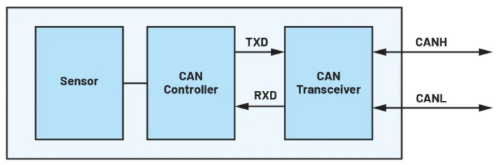
Figure 1: Single Node CAN. (Image source: ADI)
The CAN controller is responsible for handling the data link layer of communication, while the CAN transceiver handles the physical layer. The physical characteristics of the CAN transceiver will be briefly introduced later.
In the CAN protocol, a logical 0 is called a dominant bit, while a logical 1 is called a recessive bit. Since CAN is a differential protocol, the voltage difference between CANH and CANL determines the logical level of the transmitted and received signals. If this voltage difference is greater than 1.5V, the CAN receiver recognizes the bit as logical 0; conversely, if the voltage difference is less than 200mV, the CAN receiver recognizes the bit as logical 1. Figure 2 shows several continuous transmission signal waveforms of the CAN transceiver, including digital logic 1 and logic 0 on the TXD pin, and equivalent CAN bus levels on the CANH and CANL pins. The RXD pin shows the receiver loopback signal, which is also based on the voltage difference between CANH and CANL.
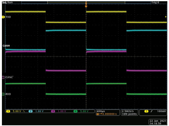
Figure 2: Physical Layer of the CAN Protocol.
The CAN data link layer establishes data frames for controlled transmission of bit streams and helps address error detection and bus contention issues. Figure 3 shows the standard frame structure of CAN.
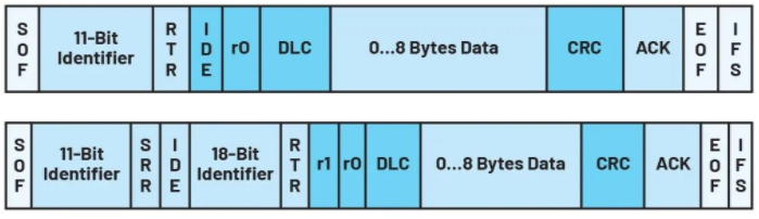
Figure 3: Data Link Layer of the CAN Protocol.
Each node begins a data frame with a frame header (SOF), which is the first dominant bit. The following 11-bit identifier is a unique address for each node. IDE indicates the frame structure. When this bit is logical 0, it indicates that CAN is in standard format, while a logical 1 indicates that CAN is in extended format. r0 is a reserved bit. The DLC field indicates the number of bytes of data to be transmitted. In the CAN 2.0 standard frame, the maximum number of bytes that can be transmitted is 8. The receiving node confirms receipt of the data frame by sending a dominant bit on the bus. Finally, there is a recessive frame tail (EOF), which marks the end of a data frame.
In most cases, when selecting a CAN transceiver for evaluation, users assess the transceiver by sending a bit stream on the TXD pin (using a function generator). While this method is very suitable for evaluating single-node CAN, it seems to have drawbacks when developing multi-node, long-distance CAN systems. Therefore, to select a suitable CAN transceiver for the system, it is necessary to conduct new types of tests on CAN controller and transceiver systems for the following reasons:
Arbitration
The main reason for this system-level testing approach is the arbitration characteristics of the CAN protocol. If two nodes attempt to occupy the bus simultaneously, non-destructive bit-wise arbitration is used to achieve access. The node that sends the first dominant “0” identifier bit retains control of the CAN bus, and the CAN bus continues to complete its message transmission (while the other node sends a recessive “1”). Figure 4 illustrates this arbitration scheme between two nodes.
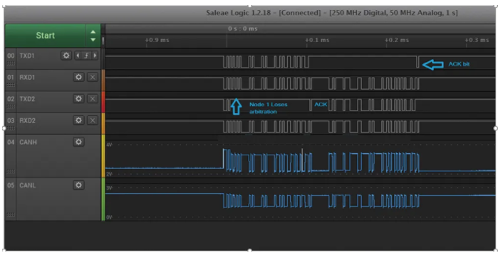
Figure 4: CAN Arbitration in a Dual Node System.
In Figure 4, Node 1 and Node 2 are interconnected via the CAN bus. Therefore, the CANH and CANL signals are shared between the two nodes. TXD1 and RXD1 are signals for Node 1, while TXD2 and RXD2 are for Node 2. As seen in the figure, the first three bits of Node 1 and Node 2 are the same, namely 1, 0, 1. Note the fourth bit: Node 2 has a recessive bit, while Node 1 has a dominant bit. Since Node 1 has the dominant bit, it wins arbitration and can continue sending the complete message. Node 2 acknowledges this message. Once Node 1 completes transmission, Node 2 begins sending its message, and Node 1 acknowledges it in turn.
Each node has a unique identifier ID. Therefore, this 11-bit identifier ID is used in the arbitration process. The controller reads these bits to identify the priority of message transmission. In CAN-FD, the arbitration bit rate can differ from the data bit rate, whereas in CAN 2.0, both are the same.
Synchronization
In traditional CAN 2.0 systems, the bit rate sometimes exceeds the recommended standard of 1 Mbps, but can only reach a maximum of 2 Mbps. In CAN-FD systems, the standard data bit rate can reach up to 10 Mbps, but for compatibility, the arbitration bit rate is still limited to 1 Mbps. Regardless of which, during the arbitration phase, including the 11-bit identifier and SOF bit, each transmitted bit will be read back for synchronization purposes.
CAN nodes synchronize on the bus observing the edges; however, the signal propagation time on the bus introduces phase shifts between different nodes. The lossless arbitration mechanism used by CAN for media access control requires that the phase shift between any two nodes be less than half a bit time. The lower boundary of the nominal bit time defines the upper boundary of the nominal bit rate and bus length. Therefore, the rise and fall times of RXD, the loop delay of the CAN transceiver, and the delays caused by the cable must all be accounted for. For high bit rates (e.g., 10 Mbps), the propagation delay and rise/fall time requirements must be less than 50 ns.
Compatibility
Since the arbitration bit rate in CAN-FD is limited to 1 Mbps, it provides higher margins for synchronization among as many nodes as possible. However, CAN-FD is a new technology that has not been adopted in all CAN systems. In some cases, there may be no CAN-FD controllers available, or customers may consider the costs too high, thus having to adopt the original standard CAN controllers. In these systems, it may be due to the critical nature of sensor information, or perhaps the cable lengths between nodes are short, which requires CAN nodes to communicate at higher bit rates (>2 Mbps). In such cases, the rise/fall time symmetry of the transceiver and propagation delay may limit the upper limit of the data communication rate.
Testing Examples
Taking the CAN transceiver MAX33012E as an example, when using a 20-meter cable, this transceiver has passed testing at rates of up to 13.3 Mbps, as shown in Figure 5.
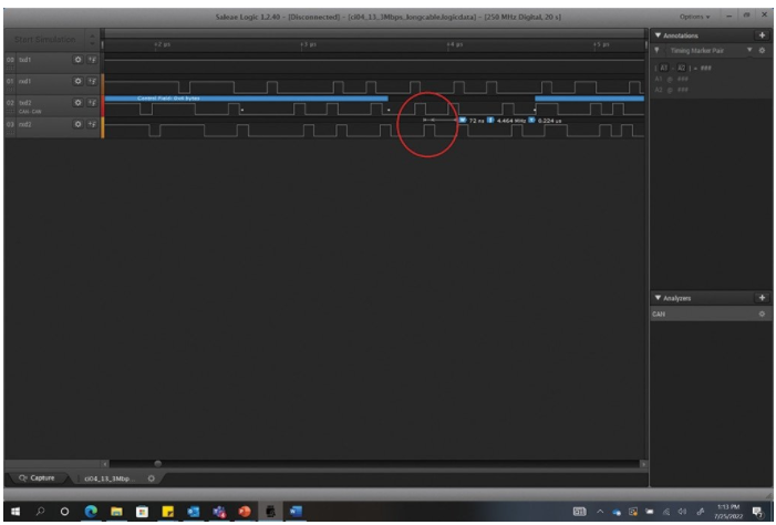
Figure 5: MAX33012E CAN Data Transmission.
In Figure 5, the TXD2 bit width is 75 ns (equivalent to 13.3 Mbps), and the RXD2 bit width is 72 ns. When the controller samples at 80% of the TXD bit width, including the required RXD rise/fall time and loop delay, the minimum RXD bit width is 60 ns. Additionally, it can be seen that the received bit width is 72 ns. Therefore, the MAX33012E meets the conditions and is robust enough to operate at higher bit rates. In this case, the CAN controller detected no errors and continued data communication.
However, compared to the successful testing example above, many CAN communication products often fail during the arbitration phase at higher transmission rates, as shown in the results of Figure 6. This test also sends a bit width of 75 ns (corresponding to 13.3 Mbps), and the received bit width is less than 80% of the transmitted bit width (48 ns). It is not difficult to see that the bit transmission fails during the arbitration phase, leading to communication errors and ultimately causing the system to stop functioning, as shown in Figure 6.
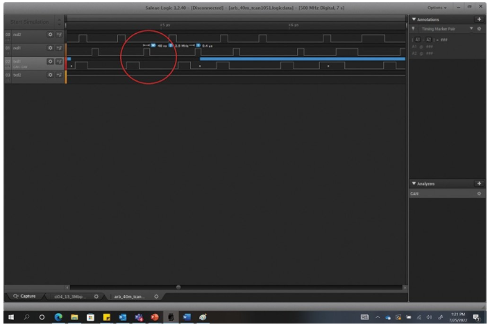
Figure 6: Illustration of Communication Data Transmission Errors in CAN.
In fact, many types of data transmission errors related to the results shown in Figure 6 can only be discovered by conducting complete system-level testing. Note that system-level testing must include all CAN controllers, CAN transceivers, and a long cable.
Conclusion
System-level testing of CAN transceivers helps to identify potential data transmission issues within the system. By evaluating CAN transceivers with CAN controllers and cables that meet timing and voltage specifications, these issues can be avoided. The robustness of the CAN system is cumulative from each component within the system. Therefore, evaluating a single CAN transceiver cannot accurately measure system functionality. Pre-validation of the system is more cost-effective than having to repair or replace components after a failure. Thus, it is extremely important to conduct system-level testing verification before selecting a CAN controller.