In the perception of most people, printed circuit boards (PCBs) are the static framework of electronic devices. However, in the field of motor engineering, engineers have developed an innovative application: using PCBs as rotors for brushless motors. This technology is not a figment of imagination but a solution tailored for specific high-performance needs, already discussed and applied in academic papers and high-end manufacturing. This week, we will objectively explore this fascinating technology.
Shenzhen Jie Chuang Li1. What is a PCB Rotor? What is the Technical Principle?
A PCB rotor, more accurately termed a “PCB winding rotor” or “printed winding rotor,” is fundamentally based on the use of PCB manufacturing processes (etching, lamination) to create precise copper foil traces on an insulating substrate (such as FR-4) to replace traditional copper wire windings.
Operating Principle: The physical principle is no different from that of traditional motors, both based on electromagnetic induction. When current flows through the copper foil coils on the PCB, a magnetic field is generated. This magnetic field interacts with the magnetic field of the motor stator’s permanent magnets, producing Lorentz force, which drives the rotor to rotate.
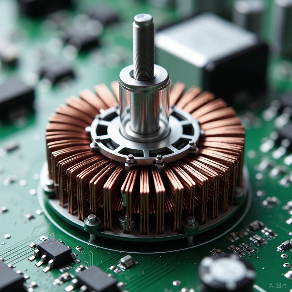
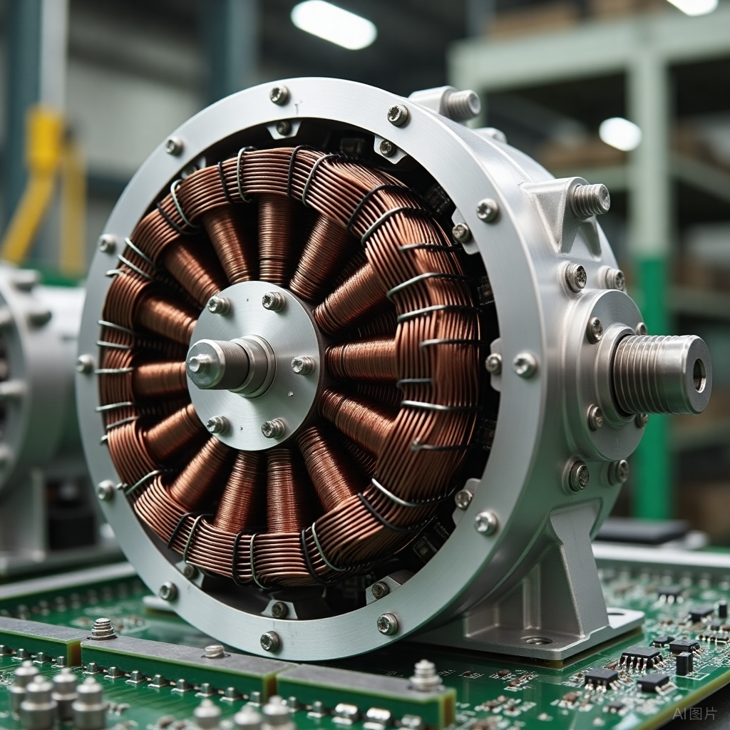
Physical Form: It typically consists of one (or multiple stacked) flat discs, visibly featuring a very regular spiral or spoke-like copper wire pattern, resembling a meticulously designed circuit.
Shenzhen Jie Chuang Li2. Advantages and Characteristics of PCB Rotors (Based on Actual Performance)
Compared to traditional enameled wire wound rotors, the advantages of PCB rotors stem from their manufacturing process:
Low Inertia and High Acceleration: This is the most significant advantage. PCB rotors are made from lightweight FR-4 material and copper foil, making them very light. According to analyses in journals such as the “IEEE Transactions on Industrial Electronics,” low inertia means the rotor can start and stop very quickly, exhibiting excellent dynamic response performance. This is crucial for applications requiring high-speed precision positioning (such as robotic joints and optical scanners).
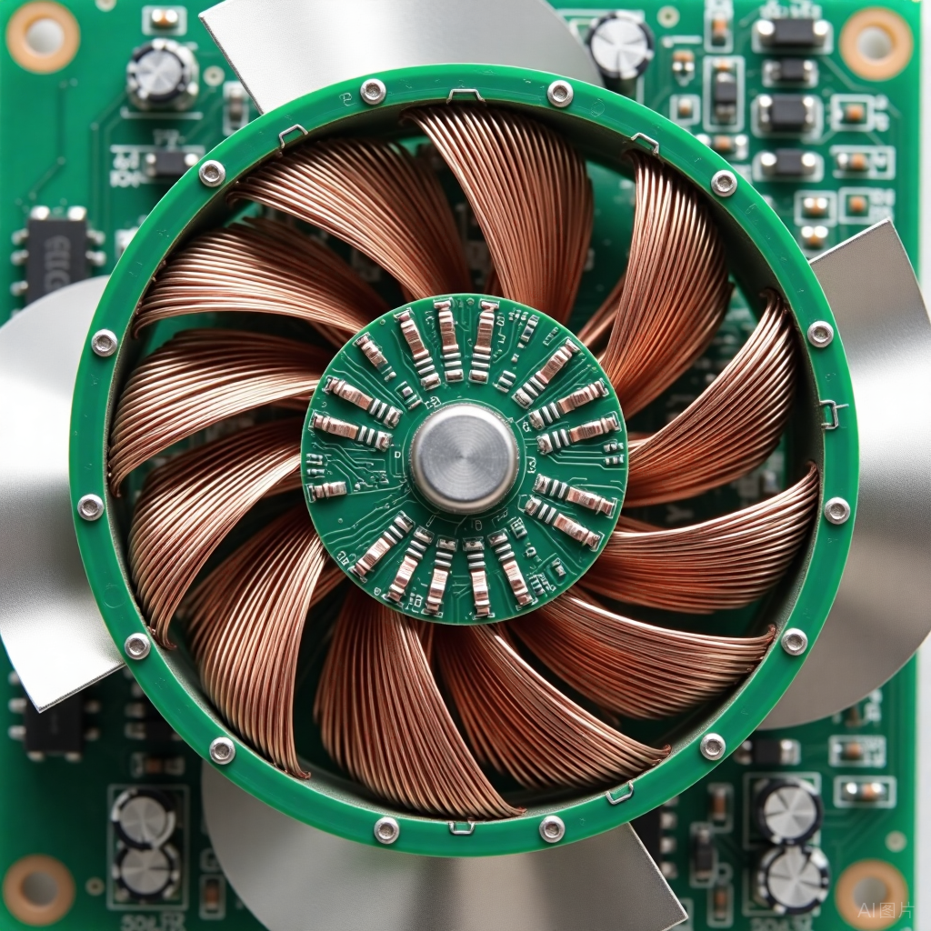
High Precision and Consistency: The manufacturing of PCBs is based on photolithography technology, allowing the coil patterns to achieve micron-level precision, with each rotor exhibiting completely consistent characteristics. This ensures extremely low torque ripple (smooth operation, minimal vibration) and good dynamic balance, which helps reduce noise and wear.
Flat Structure: The natural flat shape makes it very suitable for constructing “axial flux motors” or “disc motors.” This structure can be made very thin, providing greater flexibility in structural design for devices, suitable for space-constrained scenarios (such as drones and compact cooling fans).
Thermal Management Advantages: The flat and large surface area characteristics facilitate heat dissipation. Heat can be conducted more evenly through the PCB substrate, rather than easily forming hotspots internally as in traditional windings.
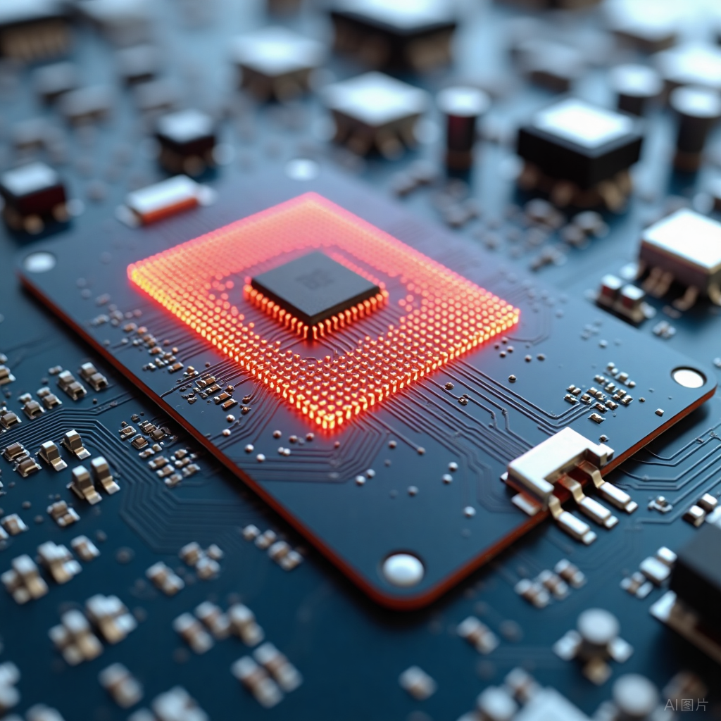
Integration Potential: This is a unique possibility brought by PCB technology. Theoretically, temperature sensors (such as NTC thermistors) or magnetic sensors (such as Hall elements) can be integrated while manufacturing the rotor PCB. This has been discussed in several technical documents, but the complexity of implementation is high, making it a frontier exploration direction.
Shenzhen Jie Chuang Li3. Technical Challenges and Limitations (Objective Analysis)
PCB rotors are not a panacea, and their limitations are equally evident, determining their application boundaries:
Power Density Limitations: This is the primary challenge. The thickness of the copper foil on the PCB is usually limited (commonly 1-4 oz, i.e., 35-140 μm), resulting in a smaller cross-sectional area of the windings, relatively high resistance, and limited current-carrying capacity. Therefore, it is not suitable for high torque and high power applications, as it may lead to severe overheating due to Joule heating (I²R losses). The thermal resistance of substrate materials (such as FR-4) also limits their operating temperature.
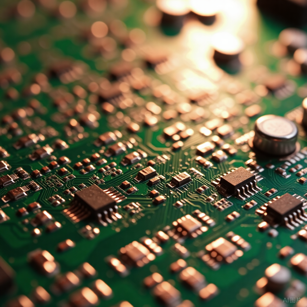
Mechanical Strength Issues: Although FR-4 material has a certain strength, at ultra-high rotational speeds, the enormous centrifugal forces may challenge the structural integrity of the PCB, requiring extremely high standards for materials and bonding processes.
Cost Factors: For mass-produced, cost-sensitive standard motors, the cost of PCB rotors may exceed that of traditional automated winding solutions. They are more suitable for high-value, performance-prioritized professional fields.
Shenzhen Jie Chuang Li4. Practical Application Areas
Based on their characteristics, PCB rotor technology is currently mainly applied in the following fields that have special requirements for performance, weight, or shape:
Drones (UAVs): Especially for propulsion motors of small drones, weight reduction can directly enhance endurance.
Precision Optical Equipment: Such as laser scanning mirrors and microscope stage drives, requiring smooth, vibration-free motion.
Industrial Automation: Joint modules of small robots (such as collaborative robots) requiring high acceleration and rapid response.
High-Performance Cooling Fans: Especially in the server and data center fields, some high-end fans are beginning to adopt this technology to seek better efficiency and noise balance.
Medical Equipment: Some small medical devices requiring high-speed rotation, such as dental handpieces.
PCB rotor technology is a distinctive and targeted innovative technology. It is not intended to replace traditional motor technology but provides an excellent solution in high-performance, lightweight, and low-inertia niche markets.
It perfectly demonstrates how cross-disciplinary thinking (applying electronic manufacturing processes to the electromechanical field) can solve specific engineering challenges. Although limited by power density and unable to be widely adopted, it plays an irreplaceable role on the stage where it excels. With advancements in material technology (such as high-temperature resistant substrates and thicker copper foils) and processes, its application prospects are promising.
Disclaimer: If there are any copyright issues, please contact us promptly. The interpretation of copyright belongs to the original author. This article is recommended for reading by Jie Chuang Li Instruments!
 Contact Number
Mobile Number: 19210061977
Shenzhen Jie Chuang Li Instruments Co., Ltd.

 Company Website
Scan to quickly enter
Shenzhen Jie Chuang Li Company Website

 Clickto read the original text, to see more