 This image was generated by AI
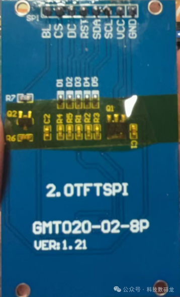 For project use, I won’t discuss the specific principles here. Let’s directly introduce the interface.
BL—————-》Backlight pin
CS—————-》Chip select pin
DC—————-》Command pin
RST—————》Reset pin
SDA—————》Data pin
SCL—————》Clock line
VCC—————》Power pin
GND—————》Ground pin
BL: Backlight pin, there are two common ways to set it, one is to supply power directly from VCC, and the other is PWM dimming, the latter is more widely used.
CS: Chip select pin, this pin needs to be pulled low during communication to select the device.
DC: Command pin, for my screen, it sends0 for commands, 1 for data
RST: Reset pin, pull high to reset
SDA: Data pin, used to send data
SCL: Clock pin, sends clock signals
When touching the screen, you can directly ask the vendor for example code, like for my screen. Now let’s look at the specific steps to light it up.
Note that hardware SPI is used here.
First, initialize the GPIO ports and SPI, be sure to check the manual to see which specific pins correspond to the SPI.
GPIO_InitTypeDef  GPIO_InitStructure1; GPIO_InitTypeDef  GPIO_InitStructure2; SPI_InitTypeDef   SPI_InitStructure;
RCC_AHB1PeriphClockCmd(RCC_AHB1Periph_GPIOA, ENABLE); RCC_APB2PeriphClockCmd(RCC_APB2Periph_SPI1, ENABLE);

GPIO_PinAFConfig(GPIOA, GPIO_PinSource5, GPIO_AF_SPI1);   //SCL
GPIO_PinAFConfig(GPIOA, GPIO_PinSource7, GPIO_AF_SPI1);  //SDA
GPIO_InitStructure1.GPIO_Pin = GPIO_Pin_5|GPIO_Pin_7; GPIO_InitStructure1.GPIO_Speed = GPIO_Speed_100MHz; GPIO_InitStructure1.GPIO_Mode = GPIO_Mode_AF; GPIO_InitStructure1.GPIO_OType = GPIO_OType_PP; GPIO_InitStructure1.GPIO_PuPd = GPIO_PuPd_UP;
GPIO_Init(GPIOA, &GPIO_InitStructure1);

GPIO_InitStructure2.GPIO_Pin =  GPIO_Pin_3| GPIO_Pin_2| GPIO_Pin_4| GPIO_Pin_1; GPIO_InitStructure2.GPIO_Mode = GPIO_Mode_OUT; GPIO_InitStructure2.GPIO_OType = GPIO_OType_PP; GPIO_InitStructure2.GPIO_Speed = GPIO_Speed_100MHz;//100MHz GPIO_InitStructure2.GPIO_PuPd = GPIO_PuPd_UP; GPIO_Init(GPIOA, &GPIO_InitStructure2); GPIO_SetBits(GPIOA, GPIO_Pin_3| GPIO_Pin_2| GPIO_Pin_4| GPIO_Pin_1); SPI_InitStructure.SPI_Direction = SPI_Direction_2Lines_FullDuplex;  SPI_InitStructure.SPI_Mode = SPI_Mode_Master;                 SPI_InitStructure.SPI_DataSize = SPI_DataSize_8b;        SPI_InitStructure.SPI_CPOL = SPI_CPOL_High; SPI_InitStructure.SPI_CPHA = SPI_CPHA_2Edge;                 SPI_InitStructure.SPI_NSS = SPI_NSS_Soft;                         SPI_InitStructure.SPI_BaudRatePrescaler = SPI_BaudRatePrescaler_2;  SPI_InitStructure.SPI_FirstBit = SPI_FirstBit_MSB;        SPI_InitStructure.SPI_CRCPolynomial = 7; SPI_Init(SPI1, &SPI_InitStructure);
SPI_Cmd(SPI1, ENABLE);
Set macros to pull special lines high and low
#define SPI_SCK_0  GPIO_ResetBits(GPIOA,GPIO_Pin_5)      // Set SCK to PA5
#define SPI_SCK_1  GPIO_SetBits(GPIOA,GPIO_Pin_5)       // Set high
#define SPI_SDA_0  GPIO_ResetBits(GPIOA,GPIO_Pin_7)      // Set SDA to PA7
#define SPI_SDA_1  GPIO_SetBits(GPIOA,GPIO_Pin_7)
#define SPI_RST_0  GPIO_ResetBits(GPIOA,GPIO_Pin_3)      // Set RST to PA3
#define SPI_RST_1  GPIO_SetBits(GPIOA,GPIO_Pin_3)
#define SPI_DC_0   GPIO_ResetBits(GPIOA,GPIO_Pin_2)      // Set DC to PA2
#define SPI_DC_1   GPIO_SetBits(GPIOA,GPIO_Pin_2)
#define SPI_CS_0   GPIO_ResetBits(GPIOA,GPIO_Pin_4)      // CS
#define SPI_CS_1   GPIO_SetBits(GPIOA,GPIO_Pin_4)
Byte sending function
void SPI_SendByte(unsigned char byte){ while(SPI_I2S_GetFlagStatus(SPI1, SPI_I2S_FLAG_TXE) == RESET); SPI_I2S_SendData(SPI1, byte); while(SPI_I2S_GetFlagStatus(SPI1, SPI_I2S_FLAG_RXNE) == RESET); SPI_I2S_ReceiveData(SPI1); // Clear reception}Command sending function
void TFT_SEND_CMD(unsigned char o_command){ SPI_DC_0; SPI_CS_0; SPI_SendByte(o_command); SPI_CS_1; //SPI_DC_1;}Data sending function
void TFT_SEND_DATA(unsigned char o_data){ SPI_DC_1; SPI_CS_0; SPI_SendByte(o_data); SPI_CS_1; }Screen initialization
void OLED_init(void) //ST7789V2{ LCD_GPIO_Init(); SPI_SCK_0; SPI_RST_0; delay_ms(150); SPI_RST_1; delay_ms(150);  TFT_SEND_CMD(0x11); //Sleep Out delay_ms(150); //DELAY120ms //--------------------------------ST7789S Frame rate setting----------------------------------// //--------------------------------ST7789S Frame rate setting----------------------------------//  TFT_SEND_CMD(0x2a); //Column address set TFT_SEND_DATA(0x00); //start column TFT_SEND_DATA(0x00); TFT_SEND_DATA(0x00); //end column TFT_SEND_DATA(0xef);
TFT_SEND_CMD(0x2b); //Row address set TFT_SEND_DATA(0x00); //start row TFT_SEND_DATA(0x28); TFT_SEND_DATA(0x01); //end row TFT_SEND_DATA(0x17);
TFT_SEND_CMD(0xb2); //Porch control TFT_SEND_DATA(0x0c); TFT_SEND_DATA(0x0c); TFT_SEND_DATA(0x00); TFT_SEND_DATA(0x33); TFT_SEND_DATA(0x33);
TFT_SEND_CMD(0x20); //Display Inversion Off
TFT_SEND_CMD(0xb7); //Gate control TFT_SEND_DATA(0x56); //35//---------------------------------ST7789S Power setting--------------------------------------//  TFT_SEND_CMD(0xbb); //VCOMS Setting TFT_SEND_DATA(0x18); //1f
TFT_SEND_CMD(0xc0); //LCM Control TFT_SEND_DATA(0x2c);
TFT_SEND_CMD(0xc2); //VDV and VRH Command Enable TFT_SEND_DATA(0x01);
TFT_SEND_CMD(0xc3); //VRH Set TFT_SEND_DATA(0x1f); //12
TFT_SEND_CMD(0xc4); //VDV Setting TFT_SEND_DATA(0x20);
TFT_SEND_CMD(0xc6); //FR Control 2 TFT_SEND_DATA(0x0f); //TFT_SEND_CMD(0xca); //TFT_SEND_DATA(0x0f); //TFT_SEND_CMD(0xc8); //TFT_SEND_DATA(0x08); //TFT_SEND_CMD(0x55); //TFT_SEND_DATA(0x90);  TFT_SEND_CMD(0xd0); //Power Control 1 TFT_SEND_DATA(0xa6); //a4 TFT_SEND_DATA(0xa1); //--------------------------------ST7789S gamma setting---------------------------------------//
TFT_SEND_CMD(0xe0); TFT_SEND_DATA(0xd0); TFT_SEND_DATA(0x0d); TFT_SEND_DATA(0x14); TFT_SEND_DATA(0x0b); TFT_SEND_DATA(0x0b); TFT_SEND_DATA(0x07); TFT_SEND_DATA(0x3a);   TFT_SEND_DATA(0x44); TFT_SEND_DATA(0x50); TFT_SEND_DATA(0x08); TFT_SEND_DATA(0x13); TFT_SEND_DATA(0x13); TFT_SEND_DATA(0x2d); TFT_SEND_DATA(0x32);
TFT_SEND_CMD(0xe1); //Negative Voltage Gamma Control TFT_SEND_DATA(0xd0); TFT_SEND_DATA(0x0d); TFT_SEND_DATA(0x14); TFT_SEND_DATA(0x0b); TFT_SEND_DATA(0x0b); TFT_SEND_DATA(0x07); TFT_SEND_DATA(0x3a); TFT_SEND_DATA(0x44); TFT_SEND_DATA(0x50); TFT_SEND_DATA(0x08); TFT_SEND_DATA(0x13); TFT_SEND_DATA(0x13); TFT_SEND_DATA(0x2d); TFT_SEND_DATA(0x32);
TFT_SEND_CMD(0x36); //Memory data access control TFT_SEND_DATA(0x00);
TFT_SEND_CMD(0x3A); //Interface pixel format //TFT_SEND_DATA(0x55); //65K //TFT_SEND_DATA(0x66); //262K RGB 6 6 6
TFT_SEND_CMD(0xe7); //SPI2 enable Enable 2 data channel mode TFT_SEND_DATA(0x00);

TFT_SEND_CMD(0x21); //Display inversion on TFT_SEND_CMD(0x29); //Display on TFT_SEND_CMD(0x2C); //Memory write}
Screen refresh test
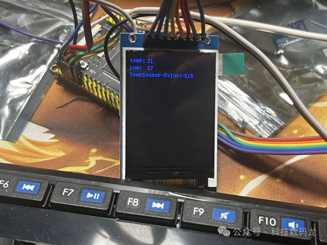
while(1) { Picture_display(point); delay_ms(200); OLED_init(); OLED_full(RED); delay_ms(1000); OLED_full(GREEN); delay_ms(1000); OLED_full(BLUE); delay_ms(1000); OLED_clear();}The final display effect is as follows; I directly used the image at the back. In fact, it should be a color refresh.