Follow our public account, click on the top right corner of the public account homepage ” ··· “, set a star mark, and stay updated with the latest news on intelligent automotive electronics and software.
Overview
The FlexRay communication bus is a deterministic, fault-tolerant, and high-speed bus system developed in collaboration with automotive manufacturers and leading suppliers. FlexRay provides fault tolerance and time-deterministic performance requirements for drive-by-wire applications (i.e., drive-by-wire, steer-by-wire, brake-by-wire, etc.). This article introduces the basics of FlexRay.
Contents
-
Growing Communication Demands
-
-
FlexRay Topology and Layout
-
-
FIBEX – FlexRay Network Database
-
PCI and PXI FlexRay Interfaces
-
Growing Communication Demands

In order for vehicles to continue improving safety, enhancing performance, reducing environmental impact, and increasing comfort, the speed, quantity, and reliability of communication data among automotive electronic control units (ECUs) must be improved. Advanced control and safety systems (which combine multiple sensors, actuators, and electronic control units) are beginning to require capabilities that exceed the synchronization and performance provided by existing standard Controller Area Networks (CAN). Coupled with the growing bandwidth demands of today’s advanced vehicles, automotive engineers need the next generation of embedded networks. After years of collaboration with original equipment manufacturers, tool suppliers, and end users, adopting new network standards in complex embedded designs such as automotive takes time. Although FlexRay will address the challenges of current high-end and future mainstream in-vehicle networks, it will not replace the other two major in-vehicle standards, CAN and LIN. To optimize costs and reduce transition challenges, the next generation of vehicles will include FlexRay for high-end applications, CAN for mainstream powertrain communications, and LIN for low-cost body electronics.
|
|
|
|
|
|
|
|
|
|
|
|
|
|
|
|
|
|
|
|
|
|
Body electronics (rearview mirrors, power seats, accessories)
|
Powertrain (engine, transmission, ABS)
|
High-performance powertrain, safety (drive-by-wire, active suspension, adaptive cruise control)
|
Understanding how FlexRay works is crucial for engineers involved in all aspects of vehicle design and production. This article will explain the core concepts of FlexRay.
Basics of FlexRay
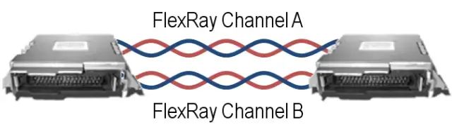
Many aspects of FlexRay are designed to reduce costs while providing optimal performance in harsh environments. FlexRay uses unshielded twisted pairs to connect nodes. FlexRay supports single-channel and dual-channel configurations, consisting of one or two pairs of wires, respectively. The differential signals on each pair of wires reduce the impact of external noise on the network without the need for expensive shielding. Most FlexRay nodes typically also have power and ground lines available to power the transceivers and microprocessors.
Dual-channel configurations provide enhanced fault tolerance and/or increased bandwidth. Most first-generation FlexRay networks only use one channel to reduce wiring costs, but as application complexity and safety requirements increase, future networks will use two channels.
FlexRay buses need to be terminated at the ends in the form of resistors between the signal wire pairs. Only the end nodes on a multi-drop bus need termination. Too much or too little termination will disrupt the FlexRay network. While specific network implementations may vary, the typical wiring impedance for a FlexRay network is between 80 and 110 ohms, and the terminal nodes are terminated to match that impedance. When connecting FlexRay nodes to test setups, termination is one of the most common causes of failure. Modern PC-based FlexRay interfaces may include onboard termination resistors to simplify wiring.
FlexRay Topology and Layout
One of the distinctions of FlexRay, CAN, and LIN from more traditional networks like Ethernet is their topology or network layout. FlexRay supports simple multipoint passive connections as well as active star connections for more complex networks. Choosing the correct topology based on the vehicle layout and level of FlexRay usage helps designers optimize the cost, performance, and reliability of a given design.
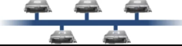
Multi-drop Bus
FlexRay is commonly used in a simple multi-drop bus topology that connects multiple ECUs with a single network cable. This is the same topology used by CAN and LIN, and it is familiar to OEMs, making it a popular topology in first-generation FlexRay vehicles. Each ECU can “branch” up to a small distance from the core “trunk” of the bus. Termination resistors are installed at the ends of the network to eliminate signal reflection issues. Because FlexRay operates at high frequencies, up to 10 Mbps compared to CAN’s 1 Mbit, FlexRay designers pay close attention to proper termination and layout to avoid signal integrity issues. The multipoint form is also very suitable for vehicle wiring harnesses that typically have similar layout types, simplifying installation and reducing wiring across the entire vehicle.
Star Network
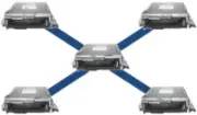
The FlexRay standard supports a “star” configuration consisting of individual links connected to a central active node. This node functions similarly to a hub in PC Ethernet. Active star configurations can run FlexRay networks over longer distances or segment the network in such a way that if a part of the network fails, it remains more reliable. If one branch is cut or shorted, other branches continue to operate. Since long-distance wires tend to conduct more environmental noise, such as electromagnetic radiation from large motors, using multiple branches can reduce the amount of exposed wiring and help improve noise immunity.
Hybrid Networks
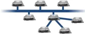
Buses and star topologies can be combined to form hybrid topologies. Future FlexRay networks may consist of hybrid networks to leverage the ease of use and cost advantages of bus topologies while applying the performance and reliability of star networks where needed in the vehicle.
The FlexRay protocol is a unique time-triggered protocol that provides options for deterministic data arriving within predictable time frames (as low as microseconds) as well as dynamic event-driven data similar to CAN to handle various frames. FlexRay achieves this hybrid of core static frames and dynamic frames by providing predefined space for static and dynamic data within preset communication cycles. This space is configured by the network designer along with the network. While CAN nodes only need to know the correct baud rate to communicate, nodes on a FlexRay network must know how all parts of the network are configured to communicate.
Like any multipoint bus, only one node can write data to the bus at a time. If two nodes write simultaneously, contention occurs on the bus, and data is corrupted. There are various schemes to prevent contention on the bus. For example, CAN uses an arbitration scheme where if a node sees a higher priority message being sent on the bus, it will yield to the other node. While flexible and scalable, this technology does not allow for very high data rates and does not guarantee timely delivery of data. FlexRay uses Time Division Multiple Access (TDMA) to manage multiple nodes. Each FlexRay node is synchronized with the same clock, and each node waits its turn to write on the bus. Because the timing in the TDMA scheme is consistent, FlexRay can guarantee the delivery of data to nodes on the network deterministically or consistently. This provides many advantages for systems that rely on the latest data between nodes.
Embedded networks differ from PC-based networks because they have closed configurations and do not change once assembled into production products. This eliminates the need for additional mechanisms to automatically discover and configure devices at run-time, much like a PC does when joining a new wired or wireless network. By designing the network configuration in advance, network designers can save significant costs and improve the reliability of the network.
To make TDMA networks like FlexRay work correctly, all nodes must be properly configured. The FlexRay standard applies to many different types of networks and allows network designers to make trade-offs between network update speeds, the amount of deterministic data, dynamic data, and other parameters. Each FlexRay network may differ, so each node must be programmed with the correct network parameters before it can participate on the bus.
To facilitate the maintenance of network configurations among nodes, the FlexRay committee has standardized the storage and transmission formats for these parameters during the engineering process. The Fieldbus Interchange Format or FIBEX file is a standard defined by ASAM that allows network designers, prototype developers, verifiers, and testers to easily share network parameters and quickly configure ECUs, testing tools, hardware-in-the-loop simulation systems, and so on for easy access to the bus.
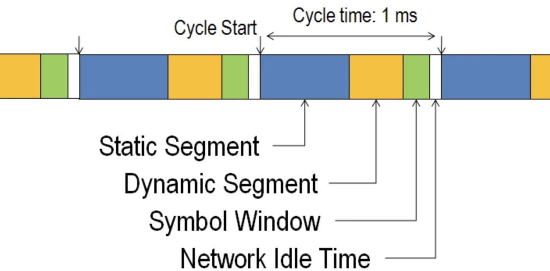
The Communication Cycle
The FlexRay communication cycle is the fundamental element of the media access scheme in FlexRay. When designing the network, the duration of a cycle is fixed, usually around 1-5 milliseconds. The communication cycle has four main parts:
Figure 1: Communication Cycle
-
Static Segment reserved time slots for deterministic data arriving at fixed cycles.
-
Dynamic SegmentThe behavior of the dynamic segment is similar to CAN and is used for broader, non-deterministic event-based data.
-
Symbol WindowUsually used for network maintenance and signaling to start the network.
-
Network Idle TimeA known “quiet” time used to maintain synchronization between node clocks.
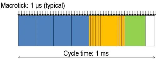
Figure 2. FlexRay Macrotick
The smallest actual time unit on a FlexRay network is the macrotick. FlexRay controllers actively synchronize and adjust their local clocks so that macrotick occurs at the same time point on each node in the network. While configurable for specific networks, macrotick is typically 1 microsecond long. Because macrotick is synchronized, data relying on it will also be synchronized.
1. Static Segment
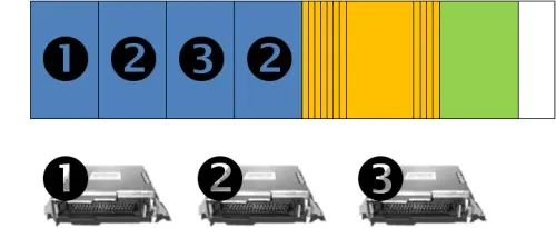
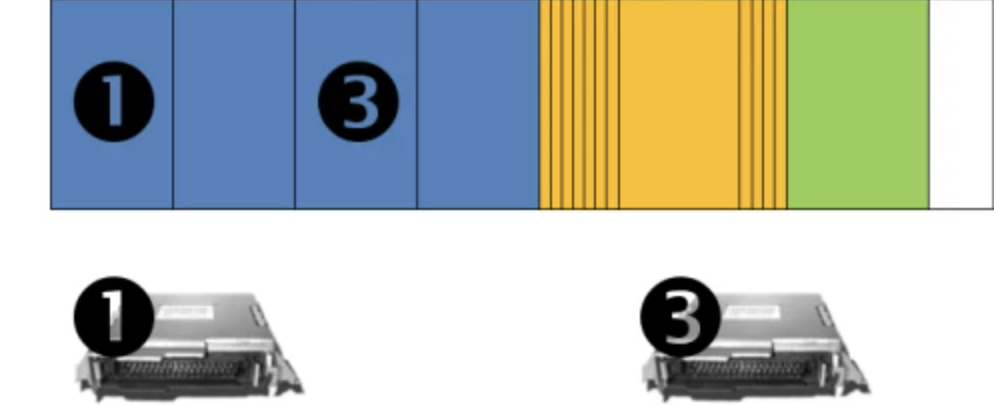
Figure 3: Static Segment Diagram with 3 ECUs Transmitting Data to 4 Reserved Slots
The static segment, represented by the blue portion of the frame, is the space used to schedule a number of time-triggered frames within the cycle. This segment is divided into multiple slots, each containing a reserved data frame. When each time slot arrives on time, the reserved ECU has the opportunity to transmit its data in that slot. Once that time has passed, the ECU must wait until the next cycle to transmit its data in that slot. Since the exact time point in the cycle is known, the data is deterministic, and programs can accurately know how old the data is. This is very useful in control loops that depend on consistently spaced data. Figure 3 illustrates a simple network where three ECUs utilize four static slots. Actual FlexRay networks can contain dozens of static slots.
Figure 4. Static Slot Diagram with ECU #2 Missing.
If an ECU goes offline or decides not to transmit data, its slot remains open and is not used by any other ECU, as shown in Figure 4.
2. Dynamic Segment
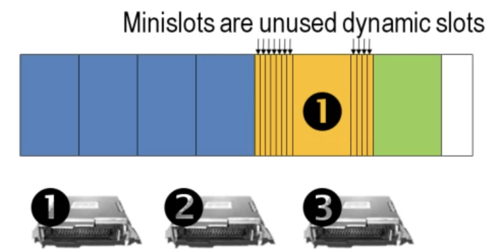
Figure 5. FlexRay Dynamic Slot Diagram with One ECU Broadcasting Data.
Most embedded networks have a small number of high-speed messages and a large number of low-speed, less critical networks. To accommodate various data without slowing the FlexRay cycle with too many static slots, the dynamic segment allows for occasional data transmission. This segment is of fixed length, so the amount of fixed data that can be placed in the dynamic segment per cycle is limited. To prioritize data, mini slots are pre-assigned to each frame of data suitable for transmission in the dynamic segment. Mini slots are typically one macrotick (1 microsecond) long. Higher priority data receives a mini slot closer to the beginning of the dynamic frame.
Once a mini slot occurs, the ECU has a brief opportunity to broadcast its frame. If it does not broadcast, it loses its position in the dynamic frame, and the next mini slot occurs. This process moves down the mini slots until the ECU chooses to broadcast data. As data is broadcast, future mini slots must wait until the ECU completes its data broadcast. If the dynamic frame window ends, lower priority mini slots must wait until the next cycle for another broadcasting opportunity.
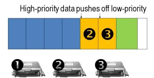
Figure 6. Dynamic Slots Diagram Showing ECU 2 and 3 Broadcasting in Their Mini Slots, Not Leaving Time for Lower Priority Mini Slots.
Figure 5 shows ECU #1 broadcasting in its mini slot because the first seven mini slots chose not to broadcast. Figure 6 shows ECU #2 and #3 using the first two mini slots, leaving no time for ECU #1 to broadcast. ECU #1 must wait for the next cycle to broadcast.
The final result of the dynamic segment is a scheme similar to the arbitration scheme used by CAN.
3. Symbol Window
The symbol window is mainly used for maintenance and identification of special cycles, such as cold start cycles. Most advanced applications do not interact with the symbol window.
4. Network Idle Time
Network idle time is a pre-defined known length. ECUs utilize this idle time to adjust for any drift that may have occurred in the previous cycle.
Data Safety and Error Handling
FlexRay networks provide scalable fault tolerance by allowing single-channel or dual-channel communication. For safety-critical applications, devices connected to the bus can use two channels to transmit data. However, when redundancy is not required, a single channel can be connected, or bandwidth can be increased by transmitting non-redundant data over two channels. At the physical layer, FlexRay provides fast error detection and signal sending, as well as error control via an independent Bus Guardian. The Bus Guardian is a mechanism at the physical layer that protects the channel from interference caused by communications inconsistent with the cluster communication schedule.
Frame Format

Figure 7. Details of the FlexRay Frame
Each slot in the static or dynamic segment contains a FlexRay frame. The frame is divided into three parts: Header, Payload, and Trailer.
Header
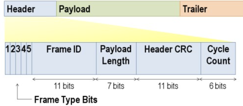
Figure 8. Bit-Level Breakdown of the FlexRay Frame
The header is 5 bytes (40 bits) long and includes the following fields:
-
-
-
-
-
The Frame ID defines the slot in which the frame should be transmitted and is used to prioritize event-triggered frames. The Payload Length contains the number of words transferred in the frame. The Header CRC is used to detect errors during transmission. The Cycle Count contains the value of a counter that increments at the start of each communication cycle.
Payload
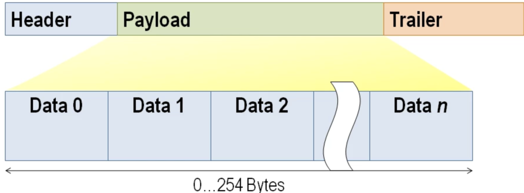
Figure 9. FlexRay Frame Payload.
The payload contains the actual data transmitted in the frame. The length of the FlexRay payload or data frame can be up to 127 words (254 bytes), which is more than 30 times longer than CAN.
Trailer
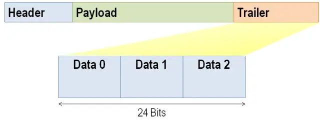
Figure 10. FlexRay Frame Trailer.
The trailer contains three 8-bit CRCs for error detection.
Signals
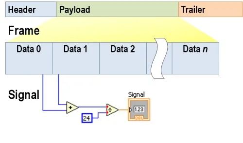
Figure 11. Frame to Signal Conversion
FlexRay data is represented in bytes. Most applications require data to be represented in decimal values with units, scales, and limits. When you retrieve one or more bits or bytes from a FlexRay frame, applying scaling and offsets results in a signal that is useful for passing actual parameters between ECUs. Most ECU programs use FlexRay data as signals and leave the conversion of signals to raw frame data to drivers or lower-level communication protocols.
Typical vehicles have hundreds or thousands of signals. As these signals’ scales, offsets, definitions, and locations may change, FlexRay networks store these definitions in the FIBEX database that defines the network. This makes programming for FlexRay networks easier, as designers can refer to the signal name in the code. Then, when the program is updated to the ECU or test system, the compiler or driver extracts the latest scaling and offset information.
Clock Synchronization and Cold Start
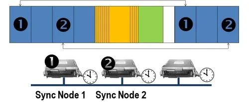
Figure 12. Simplified Synchronization Process of FlexRay Network
FlexRay has a unique ability to synchronize nodes on the network without external synchronization clock signals. To do this, it uses two special types of frames: startup frames and synchronization frames. To start the FlexRay cluster, at least two different nodes need to send startup frames. The action of starting the FlexRay bus is called a cold start, and the nodes sending startup frames are typically referred to as cold start nodes. Startup frames are similar to trigger signals that tell all nodes on the network to start.
Once the network starts, all nodes must synchronize their internal oscillators with the macro ticks of the network. This can be accomplished using two additional synchronization nodes. These can be any two individual nodes on the network that are pre-designated to broadcast special synchronization frames when the network is first powered on. Other nodes on the network wait for synchronization frames to be broadcast and measure the time between consecutive broadcasts to calibrate their internal clocks to FlexRay time. Synchronization frames are specified in the FIBEX configuration of the network.
Once the network is synchronized and online, the network idle time (the blank area in the figure) is measured and used to adjust the clocks on a per-cycle basis to maintain tight synchronization.
In-cycle Control
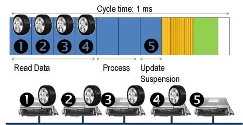
Figure 13. In-cycle Control Reading 4 Wheel Positions and Updating Vehicle Control Output in a Single FlexRay Cycle.
One advanced feature of FlexRay is its ability to perform in-cycle control. Figure 13 illustrates an example where four wheel positions are broadcast in the static slots of the frame. Because the wheel positions occur before the final update command from the central controller #5, the controller has time to process and quickly output within the same communication cycle. This allows for very high-speed control rates to be achieved on the FlexRay network.
FIBEX – FlexRay Network Database
The Fieldbus Interchange (FIBEX) format is an ASAM alliance-defined standardized XML-based file format used to describe automotive networks. As the standard format for FlexRay networks, the FIBEX database format is compatible with many different automotive protocols, making it a flexible standard. FIBEX databases are typically generated by vehicle network designers and shared with engineers working on specific aspects of the vehicle. With FIBEX files and the supporting PC interface or ECU, you can easily interact with the vehicle network without manually configuring interface and signal definitions.
FIBEX contains many aspects of the specific network, including the following:
-
Send and Receive Schedules
-
-
-
Bit-Level Encoding of Signals
-
-
-
Network Configuration, including Baud Rate and Timing
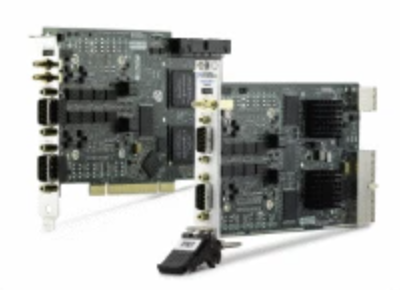
PCI and PXI FlexRay Interfaces
National Instruments provides high-performance PCI and PXI FlexRay interfaces for connecting PCs to FlexRay networks. Through PC-based interfaces, you can perform many engineering tasks on ECUs that support FlexRay, including:
-
-
Hardware-in-the-Loop Simulation
-
Bus Logging and Debugging
-
-
-
The FlexRay communication network meets the performance requirements for deterministic, fault-tolerant, and high-speed bus systems in next-generation vehicles.
Follow our public account, click on the top right corner of the public account homepage ” ··· “, set a star mark, and stay updated with the latest news on intelligent automotive electronics and software.
【Disclaimer】The article reflects the author’s independent views and does not represent the position of Wangcai Automotive Electronics. If there are issues with the content, copyright, etc., please contact Wangcai Automotive Electronics for deletion or copyright usage negotiations within 30 days of publication.