Requirements for Adding Termination Resistors
According to ISO11898-2 regulations on the value of termination resistors, a 120Ω termination resistor must be connected at both ends of the bus, totaling 60Ω on the bus, while intermediate nodes do not require termination resistors, as shown in Figure 1.
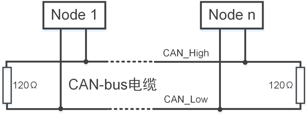
Figure 1 Termination Resistor
As shown in Figure 2, if we follow the ISO11898 standard requirements and use CANScope for testing, adding a 60Ω termination resistor, and then sending and receiving data at a baud rate of 250Kbps, we can see that the message can be sent normally, and the associated waveform is also normal.
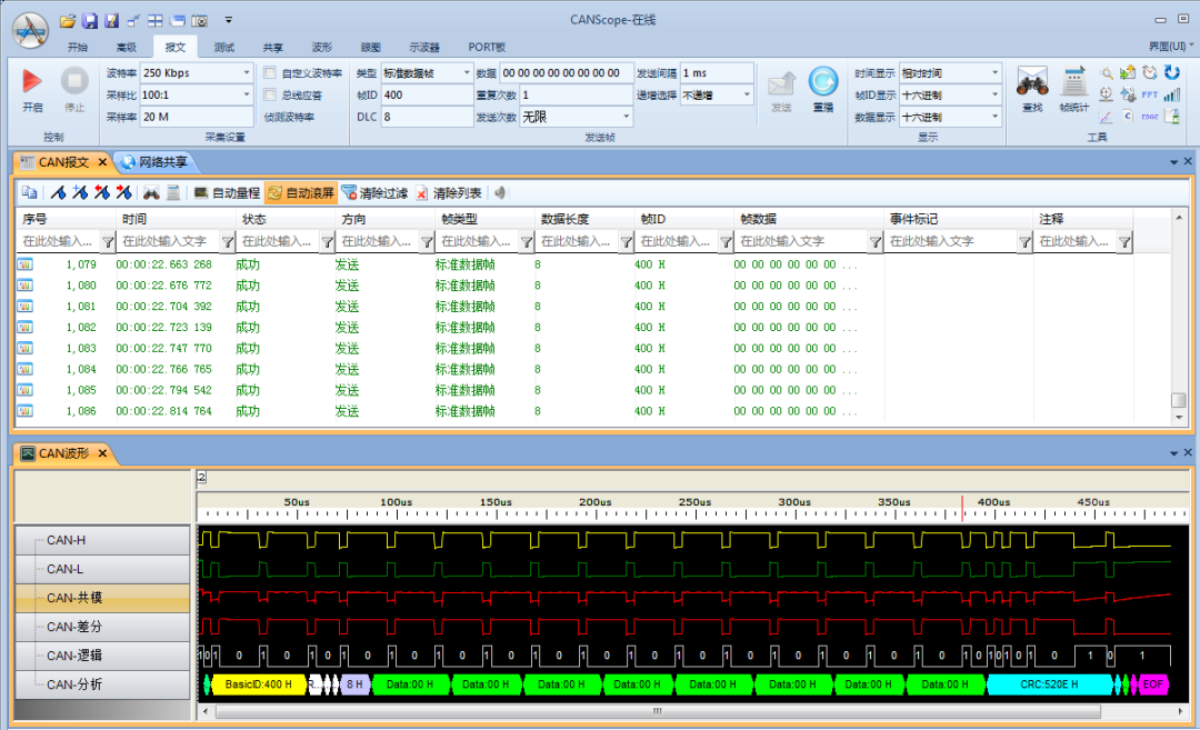
Figure 2 Adding Termination Resistor CANScope Self-Sending and Receiving Phenomenon
If CANScope sends and receives data at a baud rate of 250Kbps without adding a termination resistor, as shown in Figure 3, the sent data all have frame ID errors, and the associated waveform also shows abnormalities.
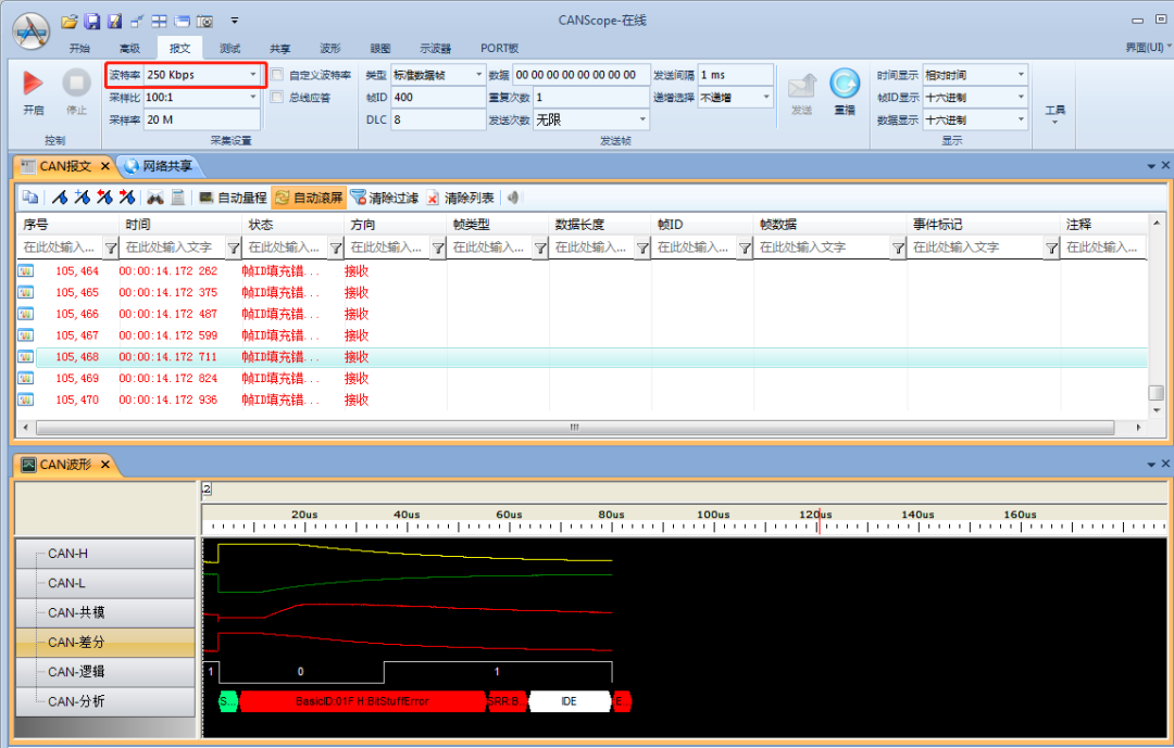
Figure 3 CANScope Self-Sending and Receiving Phenomenon Without Termination Resistor
For the message data, from the associated waveform data, we can see that the rising edge has no issues, but the falling edge is much slower compared to the waveform with the termination resistor, and it never reaches the recessive state. Why is this? Let’s analyze it one by one.
1. Why Does It Affect the Falling Edge?
As we all know, the transmission method of the CAN bus is differential transmission, and the judgment of the bus level is based on the differential voltage (CANH-CANL) between the CAN transceiver’s CANH and CANL lines. There are only two possible signal levels transmitted on the bus: one is the dominant level, and the other is the recessive level, where the dominant level represents logic 0 and the recessive level represents logic 1.
First, let’s look at the internal structure of the CAN transceiver, as shown in Figure 4:
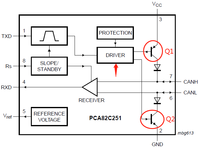
Figure 4 Internal Structure of the CAN Transceiver
When the bus level is dominant, the Q1 and Q2 inside the transceiver are in the conductive state, creating a voltage difference between CANH and CANL. When the bus level is recessive, Q1 and Q2 are in the cutoff state, and CANH and CANL are in a passive state with a voltage difference of 0. Therefore, when the recessive state changes to the dominant state (rising edge), it is mainly driven by the driver module in the transceiver; when the dominant state changes to the recessive state (falling edge), it is caused by the discharge through the entire bus and the termination resistor. Thus, the termination resistor on the bus is the main physical factor affecting the rate of the falling edge.
2. Why Does the Falling Edge Take So Long to Reach the Recessive State?
As mentioned earlier, the rate of the falling edge is influenced by the termination resistor, which relates to the time constant τ. We know that the time constant can be determined by the capacitance (C) and load resistance (R), i.e., τ=RC. Therefore, when there is no termination resistor on the bus, the resistance between CANH and CANL is very high. For example, in the case of CANScope without a termination resistor, the measured resistance is about 91KΩ. Thus, according to the time constant formula, the τ value will be very large, making it impossible to quickly dissipate the energy stored in the parasitic capacitance on the bus, leading to a slow falling edge that takes a long time to reach the recessive state.
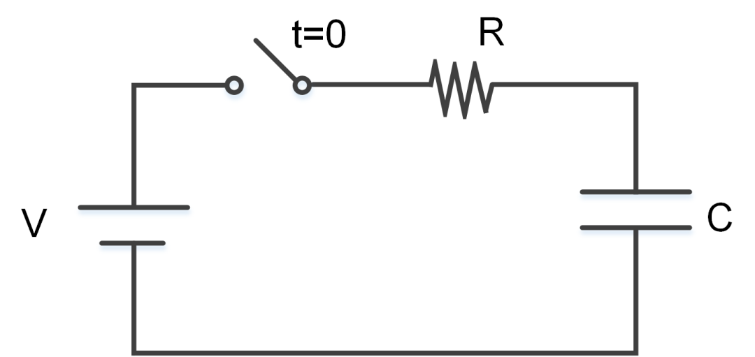
Figure 5 RC Circuit
As shown in Figure 6, this is the oscilloscope screenshot corresponding to Figure 3. From the figure, when the cursor area ΔX is one bit, i.e., 4us, the voltage YB of the differential signal at cursor B is 3.341V, which is much higher than the upper limit of the recessive level judgment of 0.5V and the lower limit of the dominant level judgment of 0.9V in the CAN specification. Therefore, this bit is judged as a dominant bit, and since the time constant is much greater than the bit time at a baud rate of 250Kbps, more than 5 bits are judged as dominant bits, thus violating the filling rules in the CAN specification and resulting in frame ID filling errors.
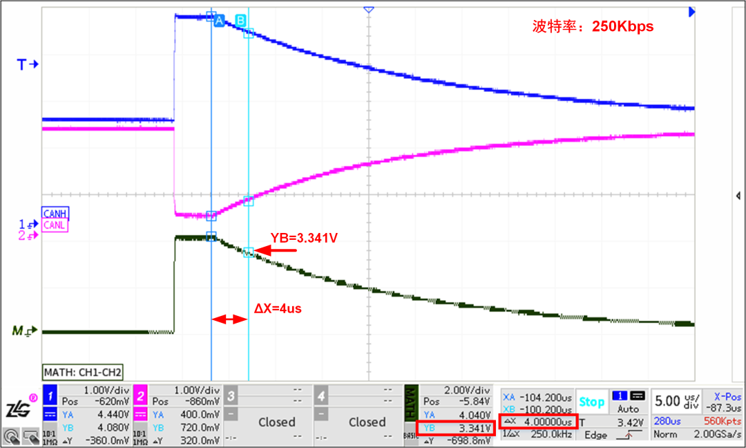
Figure 6 250Kbps Baud Rate Waveform Details
To deepen the understanding of the reasons for error frame generation, let’s take a counterexample to see what happens when the bit time is much greater than the time constant without a termination resistor.
Below, using CANScope without a termination resistor at a baud rate of 10Kbps for self-sending and receiving as an example, as shown in Figure 7, no error frames are generated in the CANScope message list. By observing the synchronized oscilloscope screenshot, as shown in Figure 8, when the cursor area ΔX is 45.6us, the voltage YB of the differential signal at cursor B is 0.4813V. Since the default sampling point of the CANScope is 75% after the cursor area, this bit can be normally judged as recessive, thus preventing the generation of error frames.
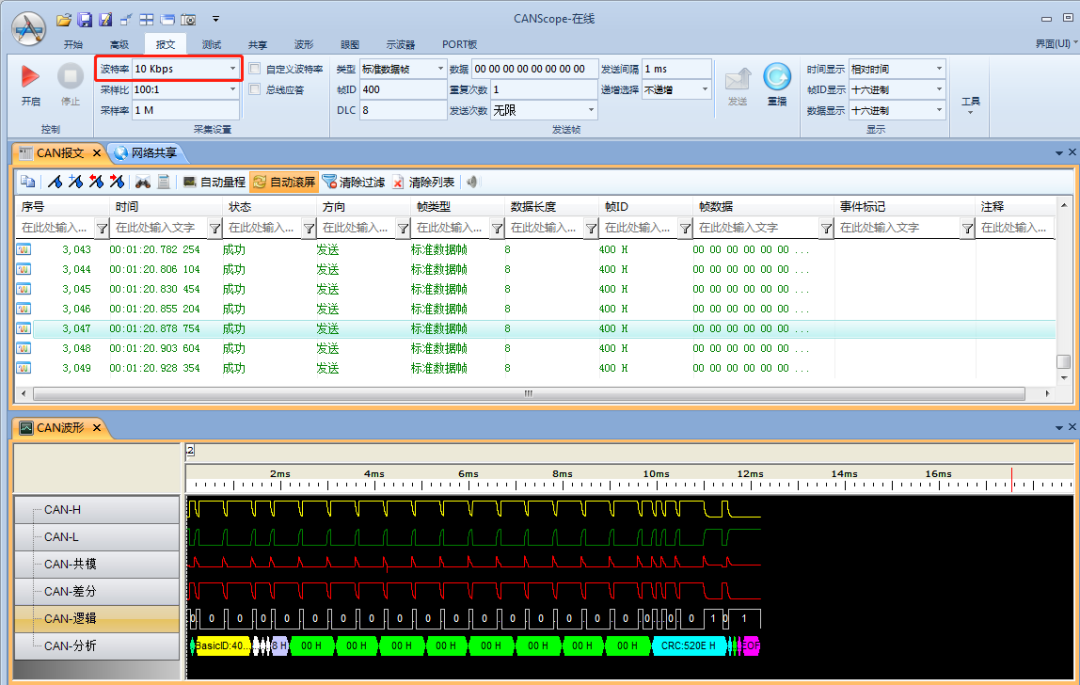
Figure7 Sending Messages at 10Kbps Baud Rate
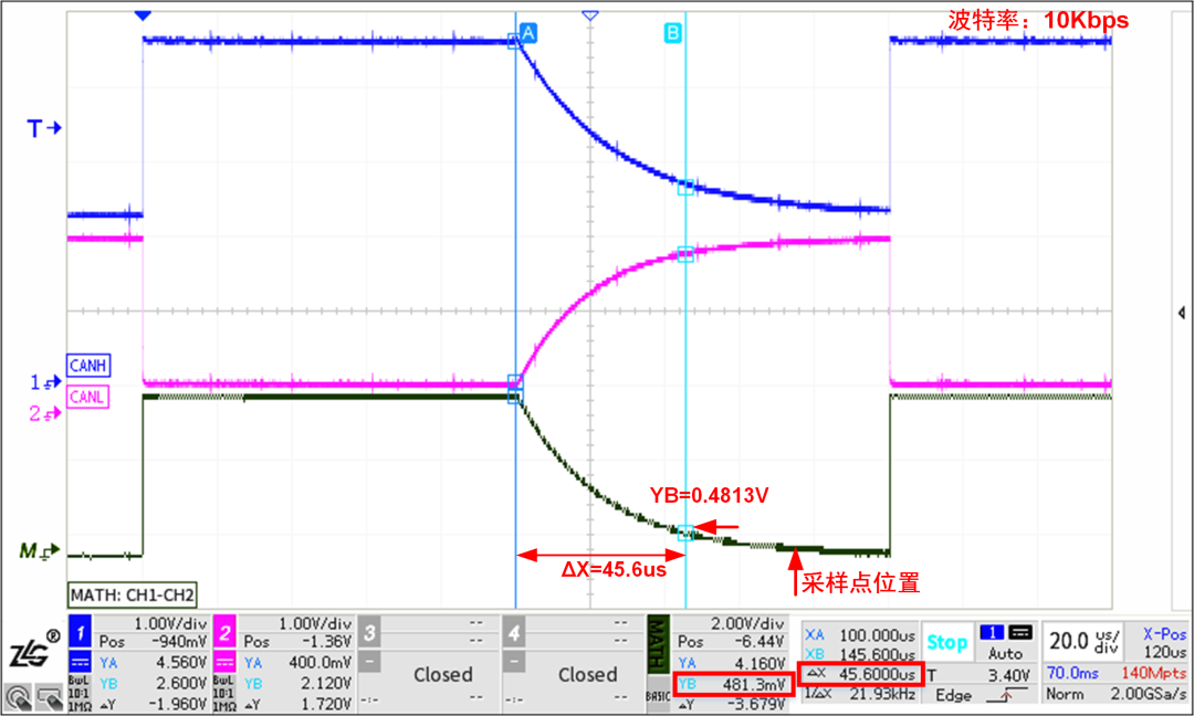
Figure8 10Kbps Baud Rate Waveform Details
Addition Methods for Termination Resistors
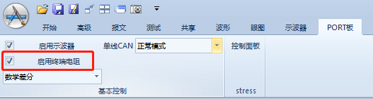
Figure 9 Standard Accessory P8251T, P1040T Termination Resistor Settings
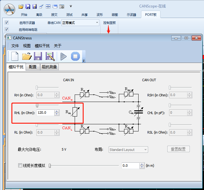
Figure 10 Optional Accessory StressZ Termination Resistor Settings
Click the mini-program below to see more repair cases