Haitao Zhang, Yaozhen Han
(Shandong Jiaotong University, School of Information Science and Electrical Engineering, Shandong Jinan 250357)
Abstract:This paper addresses the issues of short communication transmission distance and high power consumption in current combustible gas monitoring systems, and proposes a design scheme for a combustible gas monitoring system based on LoRa technology, providing the overall system design as well as detailed hardware components and prototypes. The software system is implemented using Keil software. A wireless sensor designed based on FM33LG048 collects the on-site gas concentration, communicating with the SX1278 wireless RF module and the LoRa controller; the LoRa controller, designed with the high-performance, low-power STM32F103 as the main control unit, receives, processes, and stores wireless sensor data, and provides an operational interface. The LoRa gateway in the controller acts as a relay to send the received data to the cloud platform via GPRS. The system allows local viewing of the wireless sensor data through the LoRa controller, and enables remote addition, deletion, modification, and inquiry of related information about the wireless sensors via mobile phone or computer.
Keywords:Combustible gas monitoring;LoRa;Wireless transmission;STM32 microcontroller;SX1278;Keil
Classification number:TP23;TP277 Document identification code:A
Article number:2095-1302(2022)10-0012-04
In the petrochemical industry, various flammable, explosive, toxic and harmful gases inevitably exist. If these gases leak or accumulate in the surrounding environment for a long time, they may cause serious accidents such as fires, explosions or poisoning. Therefore, monitoring combustible gases is a crucial aspect of safe production. With the development of the Internet of Things, the application of wireless network technology in combustible gas monitoring systems is becoming increasingly widespread. Literature [1-3] uses ZigBee technology to transmit data collected by sensors to gateway nodes, where data analysis and processing is performed by the monitoring center. Literature [4-6] is based on the GPRS network, transmitting data information through IP data flow, enabling remote monitoring of combustible gases. These systems achieve remote monitoring of combustible gases using different wireless communication technologies. However, ZigBee technology cannot achieve long-distance transmission, and GPRS is prone to packet loss. To address these issues, this paper designs a combustible gas monitoring system based on LoRa, which offers advantages such as long communication distance, high signal sensitivity, and low power consumption, effectively monitoring combustible gas concentrations.
1 System Working Principle and Functions
Figure 1 shows the structural block diagram of the combustible gas monitoring system, which mainly consists of wireless sensors, LoRa controllers, and gas monitoring cloud platforms. Wireless sensors collect on-site gas concentrations, process the data, and then the LoRa module actively sends the data to the corresponding LoRa controller according to the specified communication protocol. The LoRa controller analyzes, judges, and processes the concentration data, and periodically sends it to the cloud platform. The cloud platform receives, displays the data from the LoRa controller, and immediately sends SMS notifications to relevant personnel in case of data anomalies.
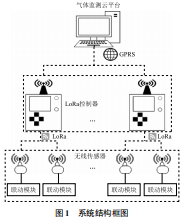 The system is divided into 3 levels, with the gas monitoring cloud platform communicating with the LoRa controller using GPRS communication; the LoRa controller and wireless sensors communicate via LoRa communication; and the wireless sensors and linkage modules communicate using RS 485 communication. The designed LoRa controller can connect to 256 wireless sensors, each with a unique identification code. To avoid channel congestion, the system defaults to a maximum of 100 wireless sensors connected to one controller.
Wireless sensors convert the collected gas concentrations into 0~5 V voltage signals, and process them into the corresponding data format. In addition, wireless sensors also have functions such as on-site digital display, zero adjustment, calibration, address change, and sound-light alarm. The linkage module consists of an electromagnetic valve and an exhaust fan; when an alarm occurs in the wireless sensor, the corresponding relay in the linkage module operates, shutting off the electromagnetic valve and starting the exhaust fan, thus preventing accidents.
The LoRa controller is the most important part of the system, and also the most challenging aspect of the system design. The LoRa controller communicates with the serial screen via 232, allowing users to view alarm times, alarm concentrations, fault types, and more, and also allows for setting, modifying, and reviewing system parameters; on the other hand, the LoRa gateway in the controller receives gas concentration information uploaded by wireless sensors, analyzes, processes, and makes judgments. It then periodically transmits the processed data wirelessly to the gas monitoring cloud platform, and immediately uploads data during on-site alarms. It can also modify parameters such as the IP address, number of wireless sensors, and upload frequency.
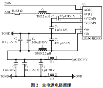
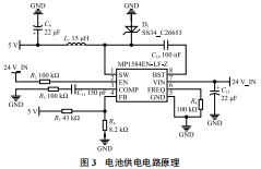
The LoRa controller mainly includes a power module, display module, and wireless communication module, with the stable-performing STM32F103RBT6 selected as the control center. The power module consists of two parts: main power supply and battery supply, with the main power supply converting AC voltage 220 V to the required DC voltage 5 V for the microcontroller via LS05-13B24R3. The LS05-13B24R3 is a compact and efficient green module power supply provided by Jinshengyang, which has advantages such as dual-use for AC and DC, wide input voltage range, high reliability, low power consumption, and safety isolation, with the main power circuit principle shown in Figure 2. The battery supply is provided by a 24 V battery, and the 24 V to 5 V DC buck circuit uses the MP1584 chip. The switch power supply achieves voltage reduction by applying a PWM switch signal to the internal MOS transistor, controlling the on-off of the MOS transistor, charging and discharging the inductor and capacitor. The battery supply circuit principle is shown in Figure 3.
The system is divided into 3 levels, with the gas monitoring cloud platform communicating with the LoRa controller using GPRS communication; the LoRa controller and wireless sensors communicate via LoRa communication; and the wireless sensors and linkage modules communicate using RS 485 communication. The designed LoRa controller can connect to 256 wireless sensors, each with a unique identification code. To avoid channel congestion, the system defaults to a maximum of 100 wireless sensors connected to one controller.
Wireless sensors convert the collected gas concentrations into 0~5 V voltage signals, and process them into the corresponding data format. In addition, wireless sensors also have functions such as on-site digital display, zero adjustment, calibration, address change, and sound-light alarm. The linkage module consists of an electromagnetic valve and an exhaust fan; when an alarm occurs in the wireless sensor, the corresponding relay in the linkage module operates, shutting off the electromagnetic valve and starting the exhaust fan, thus preventing accidents.
The LoRa controller is the most important part of the system, and also the most challenging aspect of the system design. The LoRa controller communicates with the serial screen via 232, allowing users to view alarm times, alarm concentrations, fault types, and more, and also allows for setting, modifying, and reviewing system parameters; on the other hand, the LoRa gateway in the controller receives gas concentration information uploaded by wireless sensors, analyzes, processes, and makes judgments. It then periodically transmits the processed data wirelessly to the gas monitoring cloud platform, and immediately uploads data during on-site alarms. It can also modify parameters such as the IP address, number of wireless sensors, and upload frequency.
The LoRa controller mainly includes a power module, display module, and wireless communication module, with the stable-performing STM32F103RBT6 selected as the control center. The power module consists of two parts: main power supply and battery supply, with the main power supply converting AC voltage 220 V to the required DC voltage 5 V for the microcontroller via LS05-13B24R3. The LS05-13B24R3 is a compact and efficient green module power supply provided by Jinshengyang, which has advantages such as dual-use for AC and DC, wide input voltage range, high reliability, low power consumption, and safety isolation, with the main power circuit principle shown in Figure 2. The battery supply is provided by a 24 V battery, and the 24 V to 5 V DC buck circuit uses the MP1584 chip. The switch power supply achieves voltage reduction by applying a PWM switch signal to the internal MOS transistor, controlling the on-off of the MOS transistor, charging and discharging the inductor and capacitor. The battery supply circuit principle is shown in Figure 3.
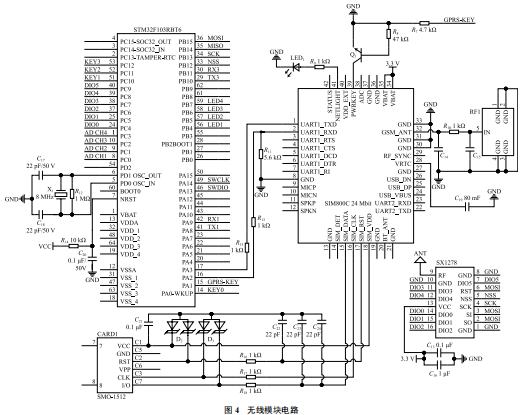
 The wireless module consists of the LoRa gateway and the GPRS module, with the main circuit principle shown in Figure 4. The LoRa gateway uses the SX1278 RF chip produced by SEMTECH. The SX1278 RF chip is a half-duplex transceiver with low to medium frequency, featuring high sensitivity, low power consumption, and anti-interference characteristics. It adopts a star network architecture, capable of connecting millions of wireless sensor nodes to the LoRa gateway [7]. All important parameters of the RF front end and digital state machine can be configured via an SPI interface, allowing access to the configuration registers of 1278. When using SX1278, two points must be noted: first, ensure common ground connection when connecting to the MCU; second, the RST pin is the reset pin of the SX1278 wireless module, active at low level, and this pin must not be used after successful initialization. The operating frequency of SX1278 is 433 MHz, with longer transmission distance and wider coverage at lower frequencies under the same transmission power [8]. The GPRS module uses the SIM800C provided by SIMCom, which is designed with power-saving technology, having a low current of 0.6 mA in sleep mode [9]. The TXD and RXD of the SIM800C are connected to the serial port 2 of the MCU, and printing is done via serial port 1 of the MCU.
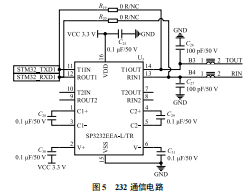
 The display module uses the Diwen DGUS screen, communicating with the microcontroller via 232, with the circuit principle shown in Figure 5. The DGUS screen mainly decomposes the GUI into controls and configures them by page. Control display is controlled by variables [10], and after configuring the control file via PC software and downloading it to the DGUS screen, the corresponding changes in control display can be achieved by rewriting variable values through the serial port.
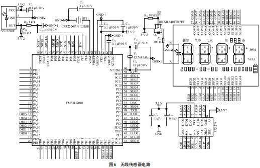
 The wireless sensor mainly completes the collection of on-site gas concentrations and data transmission, with the circuit principle shown in Figure 6. It uses a 5 V high-performance lithium battery for power supply, and when the battery voltage drops to 3.3 V, the buzzer continuously alarms for 10 s to remind the user. The microcontroller of the wireless sensor uses the FM33LG048, which is based on the ARM32 Cortex-M0+ core, with on-chip memory including 256 KB FLASH and 32 KB RAM, integrating a low-power hardware clock, and a built-in LCD display driver. The unique ultra-low power architecture design allows the chip to consume only 250 μA at a sampling rate of 1 MS/s. The infrared remote control module uses the VS1838B, enabling zero adjustment and calibration of the wireless sensor.
3.2 LoRa Main Controller Software Design
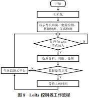
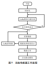
Before entering the loop, the microprocessor and chip are initialized, and the boot screen is displayed for 3 min, during which power detection, button detection, and screen detection are continuously performed. After successful booting, the LoRa gateway is powered on, and it scans to check if there are any LoRa nodes joining. Once the LoRa nodes join, the controller analyzes the received data, which is primarily categorized into normal, fault, and alarm states, then sequentially extracts the corresponding gas concentration and state bits from the protocol in the wireless sensors, storing them in the FLASH. Under normal conditions, the upload time is 6 h, but if it is a fault or alarm state, it uploads immediately. To reduce system power consumption, the system enters sleep mode until the upload time is reached. The key value detection and processing part mainly detects whether the screen responds, and whether relevant operations can be performed based on the corresponding key values. The screen interface is divided into three levels of permission operation directories, with several dropdown interface options under each level of permission, and these operational functions are completed in the key data processing function.
The wireless sensor mainly completes the collection of on-site gas concentrations and data transmission, with the circuit principle shown in Figure 6. It uses a 5 V high-performance lithium battery for power supply, and when the battery voltage drops to 3.3 V, the buzzer continuously alarms for 10 s to remind the user. The microcontroller of the wireless sensor uses the FM33LG048, which is based on the ARM32 Cortex-M0+ core, with on-chip memory including 256 KB FLASH and 32 KB RAM, integrating a low-power hardware clock, and a built-in LCD display driver. The unique ultra-low power architecture design allows the chip to consume only 250 μA at a sampling rate of 1 MS/s. The infrared remote control module uses the VS1838B, enabling zero adjustment and calibration of the wireless sensor.
3.2 LoRa Main Controller Software Design
Before entering the loop, the microprocessor and chip are initialized, and the boot screen is displayed for 3 min, during which power detection, button detection, and screen detection are continuously performed. After successful booting, the LoRa gateway is powered on, and it scans to check if there are any LoRa nodes joining. Once the LoRa nodes join, the controller analyzes the received data, which is primarily categorized into normal, fault, and alarm states, then sequentially extracts the corresponding gas concentration and state bits from the protocol in the wireless sensors, storing them in the FLASH. Under normal conditions, the upload time is 6 h, but if it is a fault or alarm state, it uploads immediately. To reduce system power consumption, the system enters sleep mode until the upload time is reached. The key value detection and processing part mainly detects whether the screen responds, and whether relevant operations can be performed based on the corresponding key values. The screen interface is divided into three levels of permission operation directories, with several dropdown interface options under each level of permission, and these operational functions are completed in the key data processing function.
After entering the loop, it is important to ensure that power circuit detection is performed after each function processing is completed.
The LoRa controller uses a 4G long connection mode, establishing a connection with the cloud platform via TCP. Upon the first connection or reconnection after disconnection, it first sends a login frame, waiting for a response from the cloud platform, and if there is no response after a timeout and two retries, the server is automatically disconnected, and connection resources are released; if a response is received from the cloud platform, the system enters normal working flow, uploading data according to the upload cycle set by the LoRa controller. When there is no data transmission, the connection is disconnected.
If there are consecutive 5 connection failures, the counter starts counting, the module re-powers on and initializes, and when the counter reaches 10, it resets and triggers an alarm, with the blue indicator light staying on, reminding the user of the network failure. The working flow of the LoRa controller is shown in Figure 8.
The combustible gas monitoring system based on LoRa technology can effectively monitor various combustible gases, with improvements in communication distance transmission and power consumption performance, realizing safe cloud monitoring of combustible gases, and enhancing the real-time and reliability of the overall regional combustible gas monitoring system.
References
[1] Huang Qinglong, You Shengyu, He Yueshun . Design of a Combustible Gas Monitoring and Alarm System Based on ZigBee Technology [J]. Internet of Things Technology, 2021, 11(7):18-19.
[2] Zhang Peng, Qin Feizhou . Indoor Combustible Gas Monitoring System Based on ZigBee Technology [J]. Computer Knowledge and Technology, 2015, 11(27):204-205.
[3] Song Shaocheng . Hardware Design of Intelligent Alarm Terminal for Chemical Combustible Gas and Toxic Gas Based on ZigBee [J]. Heilongjiang Science and Technology Information, 2013, 17(27):91
[4] Bao Liang, Wang Liao, Chen Meng, et al.. Design and Implementation of a Remote Online Monitoring System for Combustible Gas in Drainage Pipes Based on GPRS [J]. Water Supply and Drainage, 2009, 45(s1):445-448.
[5] Gan Ping, XU Zihang, Hu Guowen, et al.. Research and Design of a Remote Combustible Gas Detection System Based on GPRS [J]. Laboratory Research and Exploration, 2013, 32(9):54-56.
[6] Yan Chengzhi . Design of a Combustible Gas Monitoring System for Septic Tanks Based on GPRS [J]. Wireless Interconnection Technology, 2016, 13(16):65-66.
[7] Li Shijie, He Yigang, Luo Qiw, et al.. Design of Temperature and Humidity Monitoring Terminal for Electrical Equipment Based on LoRa [J]. Sensors and Microsystems, 2018, 37(4):89-91.
[8] Zhang Qin, Dai Yang, Yang Shenglong, et al.. Design of a Low-Power Aquaculture Water Quality Monitoring System Based on LoRa [J]. Sensors and Microsystems, 2019, 38(11):96-99.
[9] Zhang Jianliang, Wu Yue, Qi Donglian, et al.. Design of a Microgrid Comprehensive Energy Control Experimental Platform Based on DSP [J]. Laboratory Research and Exploration, 2018, 37(2):83-86.
Haitao Zhang(1995—),male,graduate student,research direction is embedded development.
Yaozhen Han(1984—),male,professor,main research directions include modern energy control technology and new energy system control.