Introduction to Oscilloscopes
Oscilloscopes are fundamental tools for detecting voltage variations over time. They are particularly suitable for displaying the shape of baseband pulses. The performance parameters of oscilloscopes can be traced back to the characteristics of early radar pulses. Real-time oscilloscope bandwidths can reach up to 33GHz, designed to capture and display repetitive or single signals.
Traditional oscilloscopes display baseband pulses very well. On a 33GHz bandwidth oscilloscope, pulses with very fast rise times or very short durations (sub-nanosecond or shorter) can be accurately observed. The triggering system of oscilloscopes is highly advanced and will be discussed in detail later.
Since most oscilloscopes have 8-bit digitizers, careful consideration of dynamic range and effective number of bits (ENOB) is required if large signals are to be measured simultaneously.
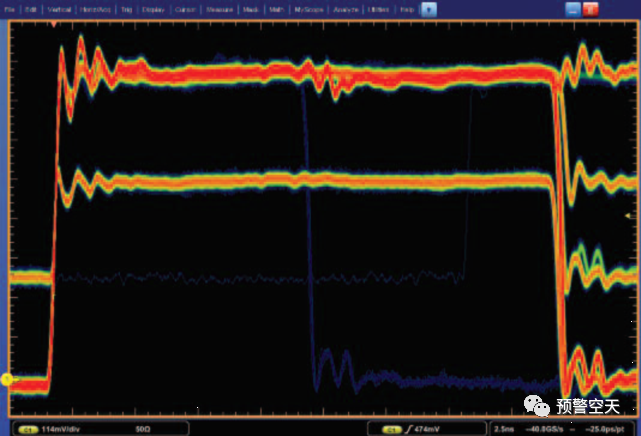
Figure 1 shows a narrow pulse among thousands of pulses
The FastAcq feature of oscilloscopes uses DPX™ acquisition technology to operate on real-time time-domain data. All frequency-domain measurements are conducted on the time-sampled data stored. The FastAcq display on the oscilloscope can reveal transient errors in baseband pulse time domains. Figure 1 only shows one pulse, which is narrower than hundreds of thousands of correct pulses. The blue area on the temperature scale indicates the lowest frequency of occurrence of the signal, while the red area represents the same signal part occurring every time.
The FastAcq feature on the DPO, DSA, and MSO series provides time-domain displays with high waveform capture rates. The DPX acquisition technology processor operates directly on the real-time digital samples from the A/D converter. It detects fast changes or single events in the time-domain display.
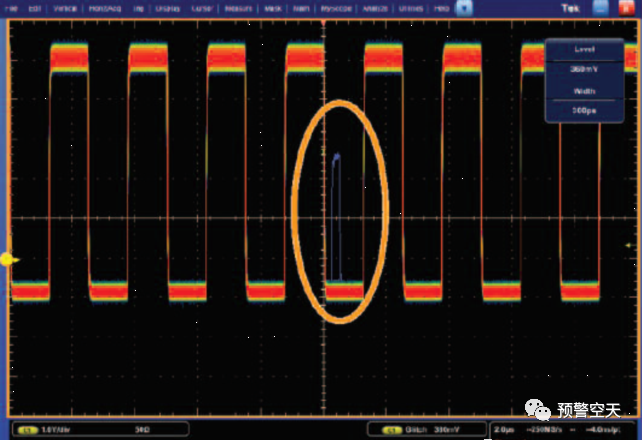
Figure 2 shows a transient fault discovered among a series of pulses
For broadband measurements using oscilloscopes, FastAcq can use voltage-time displays to view even instantaneous transient events. Figure 2 shows a blue transient event. For this display, blue represents a low occurrence transient, while red indicates the repeating parts of the waveform.
Triggering: One of the Most Advanced Features of Oscilloscopes
One of the most advanced features of oscilloscopes is triggering. The latest advancements in oscilloscope triggers have made it possible to trigger acquisitions or measurements based on voltage and voltage changes from one or multiple channels. These ranges vary from simple edge or voltage level triggers to complex logic and timing comparisons across all input channels.
Pattern recognition, parallel and serial triggering of “runt” or “fault” signals, and even triggering based on commercial digital communication standards can be done on oscilloscopes. The DPO/MSO5000, DPO7000, and DPO/MSO/DSA70000 series oscilloscopes allow users to specify two discrete trigger events as acquisition conditions. This is referred to as a trigger sequence, or Pinpoint™ triggering.
The main trigger or “A” trigger responds to a set of defined conditions, which can range from simple edge transitions to complex logical combinations across multiple inputs. A “B delay” trigger can then be specified to occur after a delay represented in time or events following the edge-driven trigger.
The B trigger is not limited to edge triggering. Instead, the oscilloscope allows the B trigger to select conditions from the same wide list of trigger types used by the A trigger after its delay period. Designers can now use the B trigger to find suspicious transients, such as those occurring hundreds of nanoseconds after the A trigger defines the start of the operational cycle.
Because the B trigger offers a full range of triggering options, engineers can specify, for example, the pulse width of the transient they want to find. Over 1,400 possible trigger combinations can be identified through precise triggering. The sequence can also include separate horizontal delays after an A trigger event to timely position the acquisition window. The reset trigger feature makes the B trigger more effective.
If a B event does not occur, the oscilloscope will reset the trigger after a specified time or number of cycles, rather than waiting indefinitely. In doing so, it restarts the A trigger to look for new A events without the user needing to monitor and manually reset the instrument. The system can detect transient faults less than 200ps wide. Advanced trigger types, such as pulse width triggers, can be used to capture and examine specific RF pulses as they vary over time or amplitude within a series of pulses.
Trigger jitter—key to achieving repeatable measurements—is less than one trillionth of a second (1ps) rms. For baseband pulses, edge, level, pulse width, and transition time-based triggers are of the most interest. If triggering based on events related to different frequencies is needed, the RSA series spectrum analyzers are required.
Manual Timing Methods for Radar Pulse Analysis
Traditional pulse measurements are accomplished by visually inspecting the display on the oscilloscope. This is done by observing the shape of the baseband pulse. This method allows for the measurement of timing and voltage amplitude. These measurements are sufficient because pulses are typically very simple, and baseband pulses are used to modulate the power output of radar transmitters.
If RF modulated pulses from the transmitter need to be measured, a simple diode detector is typically used to rectify the RF signal and provide a reproduction of its baseband timing and amplitude for display on the oscilloscope. Generally, oscilloscopes do not have sufficient bandwidth to directly display RF modulated pulses; if they do, the pulses are difficult to see, making it even harder to reliably generate triggers for advanced radar analysis applications.
For these baseband pulse measurements, the first measurement technique used is to intuitively record the position of the important part of the pulse on the screen and count the divisions on the screen between one part of the pulse and another. This is a process entirely performed manually by the oscilloscope operator and is therefore prone to errors.
Automated oscilloscope timing measurements have made the process of finding positions on the screen into a process of directly measuring the time and voltage of various parts of the pulse. Fully automated baseband pulse timing measurements are now available in modern oscilloscopes.
Single-key selections for rise time, fall time, pulse width, etc., are common. However, these measurements often do not focus on the envelope of the modulated radar signal. When used for pulse-modulated carriers, the utility of these measurements is limited as they are represented using the carrier of the signal rather than the detected pulse. This leads to pulse width measurements being conducted over a single carrier cycle and rise times being measured for the carrier rather than the modulated pulse.
 Source: Radar Communication Electronic Warfare Edited by: Li Lingyu Edited by: Lu Changcheng (Intern) Proofread by: Yang Xiaoshuai
 Early Warning Aerospace
Vanguard of Information Warfare
Cutting Edge of Informationization
Eyes of the Information Network
Submission Email: [email protected]

 Long press fingerprint > Recognize the QR code in the image > Add follow
↓↓↓ If you like this article, please click to see~