Click the image above  “Chuangxue Electronics” to easily follow and learn electronic knowledge.
Daily updates on technical articles in the electronics industry and the latest news on microcontrollers, allowing you to learn easily anytime, anywhere.
This experience note was originally intended to be shared while writing my reflections on the Shanda Intelligent Vehicle competition. The experience was summarized when I solved the timing system issue for my team members before the competition. However, I lost control of my thoughts and ended up writing a reflective piece instead of a technical one. Haha, I didn’t manage the transition well. So here’s the supplement, and I assure you this time I will keep it on track! (The sentimental types are hard to handle, haha).
Anyone who has played with intelligent vehicles knows that the timing system for competitions usually consists of a pair of through-beam photoelectric switches (distinguishing between through-beam and reflective types). The timing system starts timing when the vehicle first passes through the starting line’s photoelectric switch and stops timing when it passes through again, displaying the time. The basic principle is that simple, so many schools design and make their own simple timing systems. Our studio’s timing system (which can be seen in the images attached to that reflective article, made by my senior last year, and it has been running stably) adds a wireless remote control function to the timing, allowing wireless control of the start time (60s preparation and 30s car release time, which those who have participated in the competition will understand) and browsing historical times. Speaking of which, the protagonist of this article is the wireless remote control module, so let’s get into the topic:
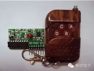
The wireless remote control module most commonly found in the electronics market consists of a 315M transmitter/receiver unit (some are 433M, but they are rare) + PT2262/PT2272 (or SC2262/SC2272, compatible) wireless transceiver module, generally used in car anti-theft keys (high-end ones no longer use this), garage controls, and automatic rolling curtain devices, as shown in the image below (many people have probably seen or used it, where the A, B, C, D of the wireless key correspond to the states of the four pins on the receiver). To understand it in depth, you just need to look at the manuals for PT2262 and PT2272; it’s not difficult. When I first encountered it in my sophomore year, I used them to make infrared encoding and decoding (2262 is encoding, and 2272 is decoding; among them, 2272M does not have latching, while 2272L has latching). Later, I directly used the module to make a remote-controlled MP3 player (I remember how comfortable it was to lie in bed and remotely control the MP3 player under the bed to change songs and adjust the volume; my dormitory was quite cozy, which made the neighboring dorms envious, haha).

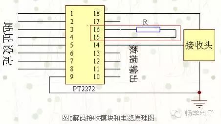
Before the competition this time, my junior came to me saying that the wireless key that matched the timing system was lost. My first reaction was to casually find another wireless key (there are many spare ones in the lab, haha), change the address to match the receiver module on the timing system, and it would be fine (here’s a side note: the wireless remote control module’s factory default address is “empty”. The 2272 decoding of the 2262 requires both addresses to be the same, and their address states can be “0”, “1”, or “empty”. Generally, a well-made module will have 8 pins for address coding, so theoretically, there can be 3^8 possible addresses for wireless modules. The pin diagram is shown below).
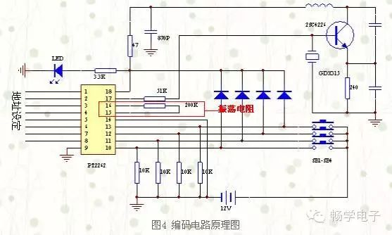
Without hesitation, I first opened the timing system to check the address of the receiver module, then casually found a wireless key, opened it up, changed the address to match the receiver module, and confidently powered it on for testing. The result was that the signal did not match. This was completely unexpected because I always thought that this would work without considering other factors, and I really couldn’t imagine that such a simple circuit could still have issues. However, after calming down and analyzing the problem carefully, I did some research online and finally discovered that the issue was due to oscillation frequency mismatch. In other words, to successfully encode and decode between 2262 and 2272, in addition to matching addresses, the oscillation frequencies must also match. The degree of matching of the oscillation frequency determines the receiving distance of the wireless remote control module and even whether it can receive the signal. Note that the oscillation frequency here is not the 315M of the transmission/reception unit, but the oscillation frequency required for encoding and decoding by 2262/2272, which is determined by the external oscillation resistor connected to the 2262/2272 chip, as shown in the image below. However, the oscillation resistors for 2262 and 2272 are not the same size. Some manufacturers online provide matching tables based on actual tests, but they cannot be fully trusted because I encountered a case that matched the table but still did not work. Later, I had to try different matching resistors (only able to attempt based on the resistance values in the matching table), and finally, I succeeded in matching it. The timing system worked normally, haha, ensuring the smooth running of the competition.

Phew… Finally finished this. I intended to share it a while ago but delayed it for a few days, and my thoughts became a bit disjointed, haha. But in any case, I wrote it down, and it feels like a weight off my shoulders. Although this article narrates the process from discovering the problem to solving it in the first person, to be honest, it feels a bit like an elementary school essay. After all, the problem itself is not very difficult; I can only say it’s a small experience I went through. It might not be worth mentioning, but I felt that if I didn’t write it down, I might forget it. So I wrote it down as an experience note. Feel free to throw bricks at me, haha. Alright, enough said, I’m going to grab a drink now, to be continued~
> > > > > > > > > > > > > > > > > > > > > > > > > > > > > > > > > > > > > > > > > > > > > > > > > > > > > >
Click the upper right corner  and select
  to share to Moments.
1. On WeChat, click the upper right corner “+” and select “Add Friends” → Search for “Chuangxue Electronics” in “Find Public Accounts” to find and follow us. 2. You can also search for the WeChat ID “Chuangxue Electronics” to find and follow us.
Click the upper right icon to enter “Account Information” → “View Historical Messages”.
WeChat Name: Chuangxue Electronics updates various knowledge in the electronics industry and the latest information on microcontrollers every day. Come and start your visual feast.
WeChat Name: Chuangxue Electronics is a new type of knowledge-sharing platform where you can view the latest articles and online videos from Chuangxue Electronics, bringing you into the world of electronic engineering and technology development learning.
==> Go to www.eeskill.com to learn more!