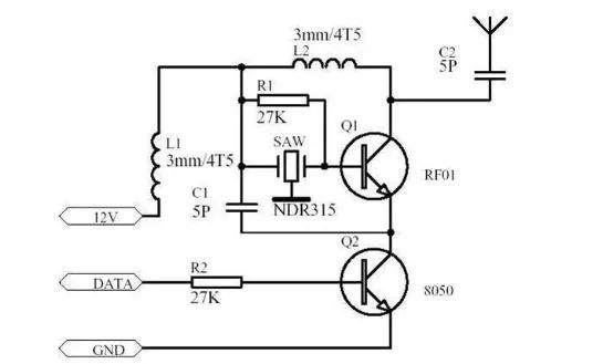
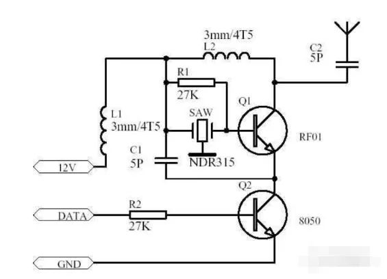
315M Transmission Circuit Principles
In a static state, 12V provides voltage to the collector of Q2 through L1, R1, and the base-emitter of Q1. When data arrives, Q2 turns on, causing the emitter of Q1 to be at 0 potential, which means Q1 is initially off.
When the emitter of Q1 is at 0 potential, Q1 turns on, making the collector signal equal to the oscillator frequency at the base.
When the DATA signal is not continuously high, Q2 is in a switching state, meaning that DATA controls when Q2 is on or off. This means that the collector signal of Q1 depends on the DATA signal, so the signal at the collector of Q1 is actually the DATA signal modulated onto the 315 MHz oscillator frequency, which is transmitted through the antenna.
How to Use the 315M Wireless Module
This design mainly focuses on a simple wireless 315M remote control transmitter-receiver design as an example, hoping to be helpful to you. Early transmitters often used LC oscillators, which suffered from significant frequency drift. The advent of surface acoustic wave devices solved this issue, achieving frequency stability similar to that of quartz oscillators, and their fundamental frequency can reach hundreds of MHz or even over a GHz. There is no need for frequency doubling, and the circuit is extremely simple compared to quartz oscillators.
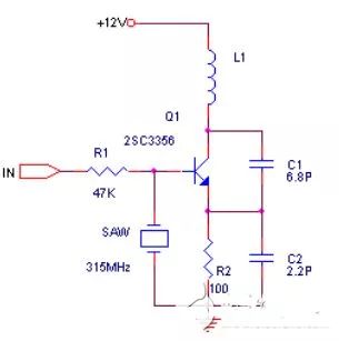
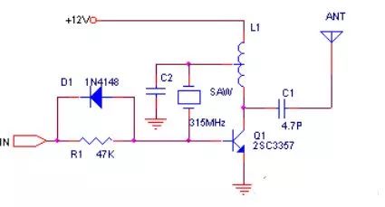
The following two circuits are common transmitter circuits. Due to the use of surface acoustic wave devices, the circuit operates very stably; even when holding the antenna, surface acoustic wave, or other parts of the circuit, the transmission frequency does not drift. Compared to the first diagram, the second has a slightly higher transmission power, reaching over 200 meters.
The receiver can use a super-regenerative circuit or a superheterodyne circuit. The super-regenerative circuit is low-cost and has low power consumption, reaching about 100uA. A well-adjusted super-regenerative circuit can achieve sensitivity similar to a first-stage amplifier, first-stage oscillator, first-stage mixer, and two-stage intermediate frequency superheterodyne receiver. However, the working stability of the super-regenerative circuit is poor, and selectivity is low, which reduces anti-interference capability. The following diagram shows a typical super-regenerative receiver:
The sensitivity and selectivity of the superheterodyne circuit can be very good. The American company Micrel has launched an integrated circuit that can complete reception and demodulation. The MICRF002 is an improved version of the MICRF001, which has lower power consumption and a power-down control pin compared to the MICRF001. The MICRF002 is stable in performance and very easy to use. Compared to the super-regenerative circuit, its disadvantage is higher cost (RMB 35). Below is its pin arrangement and recommended circuit:
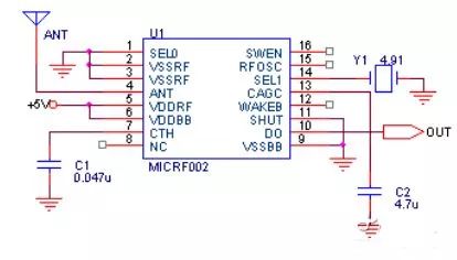
ICRF002 uses a ceramic resonator, and by changing to different resonators, the receiving frequency can cover 300-440MHz. The MICRF002 has two working modes: scanning mode and fixed mode. The scanning mode can accept a bandwidth of up to several hundred kHz, and this mode is mainly used to work with LC oscillator transmitters because the frequency drift of LC transmitters is significant. In scanning mode, the data communication rate is 2.5KBytes per second.
The bandwidth in fixed mode is only tens of kHz, and this mode is used with transmitters that use a quartz oscillator for frequency stability, allowing a data rate of up to 10KBytes per second. The working mode selection is achieved through the 16th pin (SWEN) of the MICRF002. Additionally, using the wake-up function can wake up the decoder or CPU to minimize power consumption.
The MICRF002 is a complete single-chip superheterodyne receiving circuit, essentially achieving “antenna input” followed by “data output.” The typical receiving distance is about 200 meters.
There are many forms of wireless transmission circuits using surface acoustic wave resonators. Here, we present another circuit that I referenced from an article in an electronics magazine three years ago. After combining it with the actual module introduced in that article, and after mass production, some parameters were improved. Now this product is indeed very good. However, there are many counterfeit products now, with varying quality. Because it is relatively simple, I think it is still necessary to share it with everyone. I also found many similar circuit diagrams online, but some of them have traps, so I hope everyone learns to identify some bugs.
I have not tested the absolute power of the wireless transmission of this module, but we have pulled it over distances while driving on the road, and it can reach 800 meters when paired with a standard 315M super-regenerative receiving module. Although my circuit could increase the communication distance to 1200 meters or even further by reducing the value of the base resistor of the 8050, extensive experiments have proven that this is not very reliable. The reasons are unclear; there may be two aspects: one is that when R2 is small, the 8050 has slight conduction, leading to slow cutoff of transmission.
The other reason is that if R2 is too small, the 8050 will have a relatively large conduction current, which may disturb the power supply and fail to meet the oscillation requirements. I once doubted whether my circuit was well-matched, so I specifically bought many similar modules claiming to reach 1500 meters and found that they also had the same unreliability, generally manifested as occasional failure to oscillate or baud rate not reaching 2K. Later, I increased the resistance of R2, and when it was greater than 15K, the transmission remained normal, and the distance was similar to that with 27K, so I am now using this resistor. For L1 and L2, I used 0.8mm enameled wire wound 4.5 turns on a 3mm drill bit. During production, there may still be some issues in the PCB layout, reminding everyone that the circuit should be as simple as possible, with shorter traces preferred, and good quality components should be selected. The PCB board can be 1.5mm thick.

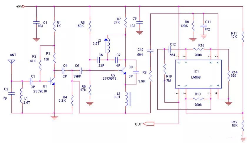
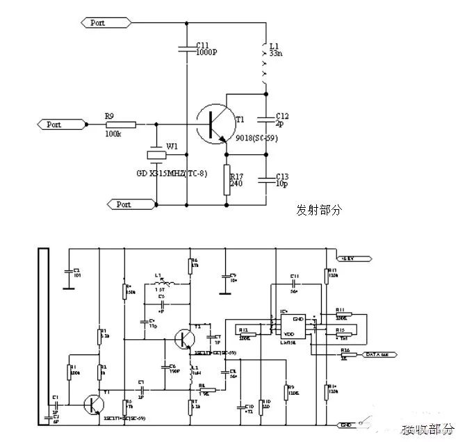
Super-regenerative receiving circuits have long been criticized compared to superheterodyne circuits, being said to have a wide bandwidth, poor anti-interference capabilities, and strong radiation, as if they are entirely inferior. However, I can clearly tell you that the vast majority of wireless receiving circuits used in anti-theft alarms on the market are super-regenerative circuits, and almost all remote control toys also use them. Therefore, it has a significant market because its sensitivity cannot be matched by superheterodyne circuits, and debugging is generally simpler than that of superheterodyne circuits. Many friends may have noticed that I used high-frequency small inductors made from PCB. Why? Because they are easier to make. Although I conducted many experimental works during the process, once confirmed, they are relatively stable.
Next, I will briefly introduce the circuit. The front loop is a PCB inductor, and the adjustable capacitor at the back is used for tuning. The tuning method is to use a spectrum analyzer to adjust the local oscillator signal to the desired 315 MHz. If you do not have a spectrum analyzer, you can tune it by receiving the transmission until you can receive it. The weak data signal passes through a 10K resistor and a 10UF capacitor into the base of T2, where it is initially amplified and then enters the LM358 for further shaping and amplification. The amplified digital signal is directly input to pin 14 of the PT2272 for decoding, with output pins being 10-13 of the PT2272.
The wireless remote control transmitter T630 is a micro-transmitter with an internal open line and no signal, operating at a frequency of 265 MHz. When powered by 12V, the remote control distance is 100 meters, with a working current of only 4mA, and its size is 28X12X10mm. The wireless receiver T631 has an internal antenna and functions like a TV high-frequency head for reception and demodulation, with a typical operating voltage of 6V, a standby current of 1mA, receiving frequency of 265 MHz, and a size of only 31X23X10mm.
Using these, various wireless remote control devices can be easily made, characterized by miniaturization, long transmission distance, low power consumption, and strong anti-interference capability, conveniently replacing infrared and ultrasonic transmitters and receivers.
The circuit principle of the wireless transmitter T630 is shown in the diagram. The circuit consists of the transmitter tube V1 and surrounding components C1, C2, L1, L2, forming a 265 MHz ultra-high frequency transmission circuit, which transmits through the loop antenna L2. The antenna L2 uses silver-plated wire or enameled wire with a diameter of 1.5mm, and the antenna size is 24mm (length) X 9mm (height). The transistor V1 is selected from high-frequency transmitting tubes BE414 or 2SC3355.
The circuit principle of the wireless remote control receiver T631 is shown in the diagram. The receiving circuit mainly consists of V1, IC, etc. V1, along with C7, C9, L2, forms the ultra-high frequency receiving circuit. Fine-tuning C9 adjusts its receiving frequency to precisely match the 265 MHz transmission frequency. When the antenna L2 receives the modulated wave, it is tuned and amplified by V1, then amplified again by V2, and sent to the IC LM358 for further amplification and shaping. The output from LM358 is from pin 7, and the actual size of this printed circuit board is 31mmX23CC, with the antenna size being 27mm (length) X 9mm (height). OUT is the signal output terminal, and the transistor V1 is selected from BE415 or 2SC3355. The capacitor C9 can be a small adjustable capacitor. IC selected is LM358.
To reduce the size of the transmission and reception circuits, all resistors are chosen to be 1/8W or 1/16W metal film resistors, and electrolytic capacitors are also ultra-small, while other capacitors are high-frequency ceramic capacitors. During soldering, component leads should be cut as short as possible to ensure they are closely attached to the circuit board.
The following are two devices using surface acoustic wave transceivers, which have longer transmission distances, stronger anti-interference capabilities, and are easier to make and debug compared to the previously introduced circuits.
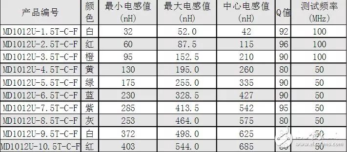
Additionally, some content regarding the inductors in the circuit:


To help everyone learn better, Changxue Electronics Network has specially added a public account for microcontrollers and EDA, pushing relevant knowledge daily, hoping to assist your studies!