
 According to industry experts such as PROCENTEC, applications based on RS-485 fieldbus technology (PROFIBUS®) are continuously growing, and industrial Ethernet (PROFINET) applications are also rapidly increasing. In 2018, a total of 61 million PROFIBUS fieldbus nodes were installed globally, with a 7% year-on-year growth in PROFIBUS process automation (PA) devices. The installation base for PROFINET was 26 million nodes, with 51 million devices installed in 2018 alone.
With the steady growth in the adoption of RS-485 fieldbus technology and the acceleration of Industry 4.0 in developing smart interconnected factories, we need to ensure continuous optimization of fieldbus technology to support intelligent systems. Optimized fieldbus technology must carefully balance EMC stability and data transmission reliability.
Unreliable data transmission can degrade overall system performance. In motion control applications, fieldbus is generally used for closed-loop position control of single or multi-axis motors. These motors typically operate in high data rate, long cable transmission scenarios, as shown in Figure 1. If position control is unreliable, actual performance will decline, leading to increased defect rates and reduced factory productivity. In wireless infrastructure applications, fieldbus is generally used for tilt/position control of antennas, making accurate data transmission crucial. Different levels of EMC protection are required in motion control and wireless infrastructure applications, as shown in Figure 1. Motion control applications often operate in electrically noisy environments, which can lead to data errors. For wireless infrastructure, protective measures must be in place to prevent indirect lightning damage in exposed environments.
Figure 1. EMC, data rate, and cable length requirements for RS-485.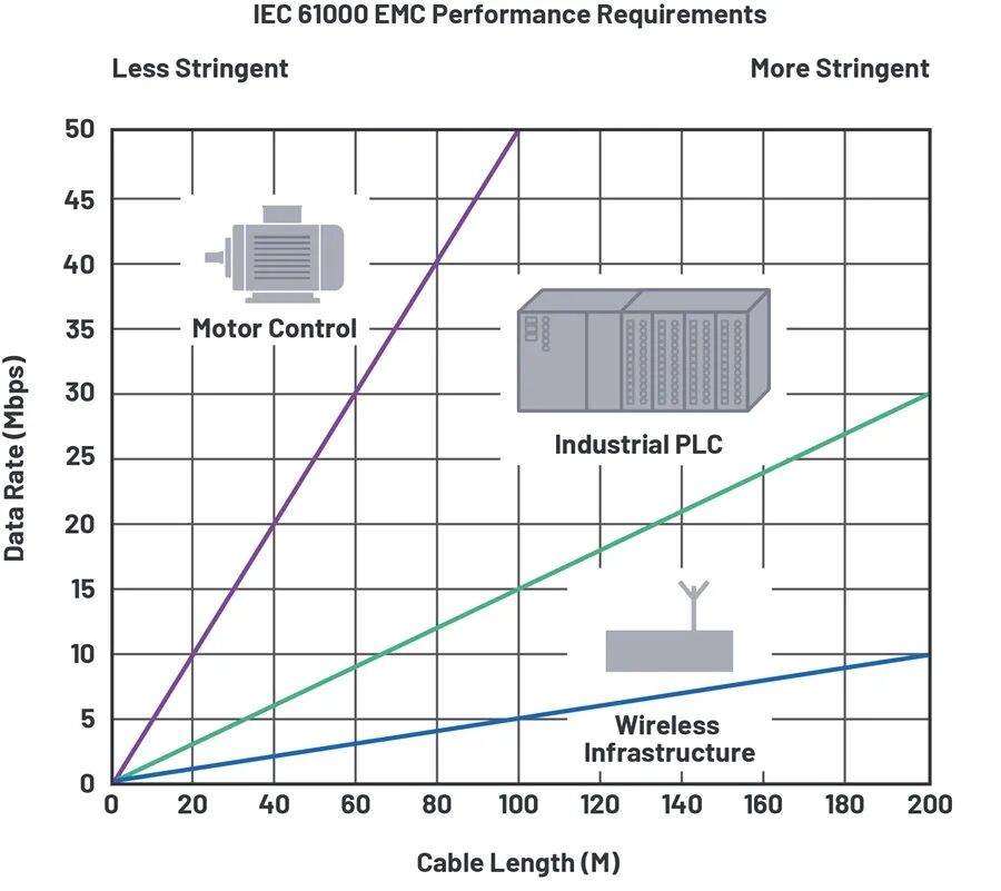
For these demanding applications, it is essential to carefully examine the cable timing performance of RS-485 transceivers to ensure system reliability and EMC characteristics. This article will introduce several important system timing and communication cable concepts; outline some key performance indicators, including clock and data distribution, and cable driving capability; and demonstrate the advantages of using the next-generation ADM3065E/ADM3066E RS-485 transceivers for industrial applications.
Timing Performance

To achieve reliable data transmission over long cables at high data rates, several important factors affecting RS-485 must be considered, such as jitter and skew, which are typically associated with low-voltage differential signaling (LVDS). Both jitter and skew caused by RS-485 transceivers and system cables need to be taken into account.
Jitter and Skew

Jitter can be quantified as time interval error; that is, the difference between the expected arrival time and the actual arrival time of a signal transition. In communication links, various factors can lead to jitter. Essentially, each factor causing jitter can be described as either random or deterministic. Random jitter can be described by a Gaussian distribution, generally arising from thermal noise and broadband scattering noise within semiconductors. Deterministic jitter, on the other hand, originates from within the communication system; for example, duty cycle distortion, crosstalk, periodic external noise sources, or inter-symbol interference. For communication systems using the RS-485 standard, with data rates below 100 MHz, deterministic jitter is more pronounced.
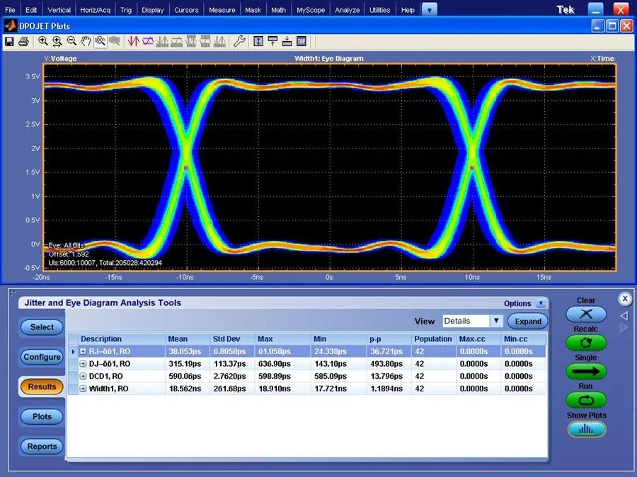
Peak-to-peak jitter is a useful metric for measuring the overall performance of system jitter caused by deterministic sources. It can be measured in the time domain by overlaying a large number of signal transitions on the same display (commonly referred to as an eye diagram). This can be achieved using an infinite persistence oscilloscope display or by using the built-in jitter decomposition software of an oscilloscope, as shown in Figure 2.
Figure 2. Time interval error, jitter, and eye diagram.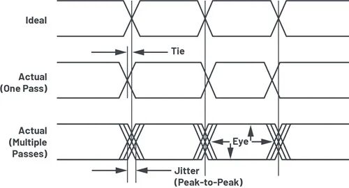
The width of the overlapping transitions represents the peak-to-peak jitter, while the blank area in the middle is referred to as the eye. This eye is the area that the receiving node can sample at the far end of the RS-485 long cable. The larger the eye width, the wider the sampling window for the receiving node, which reduces the risk of incorrectly received bits. The available eye is primarily affected by deterministic jitter from the RS-485 driver and receiver, as well as the interconnecting cable.
Figure 3 shows various sources of jitter in a communication network. In RS-485-based communication systems, the two main factors affecting timing performance are transceiver pulse skew and inter-symbol interference (ISI). Pulse skew, also known as pulse width distortion or duty cycle distortion, is a deterministic jitter generated at the transmitter and receiver nodes of the transceiver. Pulse skew is defined as the difference in transmission delay between the rising and falling edges of the signal. In differential communication, this skew can create asymmetric crossover points, resulting in mismatched durations for sending 0s and 1s. In clock distribution systems, excessive pulse skew manifests as duty cycle distortion of the transmitted clock. In data distribution systems, this asymmetry increases the peak-to-peak jitter displayed in the eye diagram. In both cases, excessive pulse skew adversely affects the signals transmitted through RS-485, reducing the available sampling window and overall system performance.
Figure 3. Major sources of jitter in RS-485 communication networks.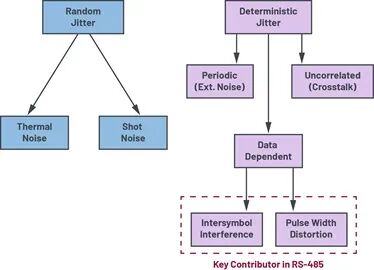
When the arrival time of a signal edge is influenced by the data pattern of that signal edge, inter-symbol interference (ISI) occurs. For applications using long cable interconnections, the effects of ISI become increasingly pronounced, making it a key factor affecting RS-485 networks. Longer interconnections create an RC time constant, where the cable capacitance is not fully charged by the end of a single bit period. In applications where the transmitted data consists solely of clock signals, this ISI does not occur. ISI can also be caused by impedance mismatches on the cable transmission line (due to improper use of stubs or termination resistors). RS-485 transceivers with high output drive capability can generally help minimize the effects of ISI, as they require less time to charge the load capacitance of the RS-485 cable.
The percentage of peak-to-peak jitter tolerance is highly application-dependent, with 10% jitter commonly used as a benchmark for evaluating the performance of RS-485 transceivers and cables. Excessive jitter and skew can affect the sampling performance of the receiving RS-485 transceiver, increasing the risk of communication errors. In properly terminated transmission networks, selecting optimized transceivers to minimize transceiver pulse skew and ISI effects is essential for achieving a more reliable, error-free communication link.
RS-485 Transceiver Design and Cable Impact

The TIA-485-A/EIA-485-A RS-485 standard provides specifications related to the design and operational range of RS-485 transmitters and receivers, including voltage output differential (VOD), short-circuit characteristics, common-mode load, input power thresholds, and ranges. The TIA-485-A/EIA-485-A standard does not specify the timing performance of RS-485 (including skew and jitter), which is optimized by IC suppliers according to product data sheet specifications.
Other standards, such as TIA-568-B.2/EIA-568-B.2 twisted pair telecommunications standards, provide background on how AC and DC affect RS-485 signal quality. This standard provides relevant considerations and testing procedures for jitter, skew, and other timing measurements, and sets performance limits; for example, the maximum skew allowed for Category 5e cable is 45 ns/100 m. ADI application note AN-1399 discusses the TIA-568-B.2/EIA-568-B.2 standards in detail, as well as the impact of using non-ideal cables on system performance.
While available standards and product data sheets provide a wealth of useful information, any meaningful characterization of system timing performance requires measuring the performance of RS-485 transceivers over long cables.
Achieving Faster and Broader Communication with RS-485

The ADM3065E RS-485 transceiver features ultra-low transmitter and receiver skew performance, making it ideal for transmitting precision clocks, typically used in motor encoding standards. The ADM3065E has been shown to exhibit deterministic jitter of less than 5% with typical cable lengths in motor control applications (Figures 4 and 5). The ADM3065E has a wide power supply voltage range, so this level of timing performance is also applicable to applications requiring 3.3 V or 5 V transceiver power supplies.
Figure 4. Typical clock jitter performance of the ADM3065E. Figure 5. ADM3065E receiving eye diagram: 25 MHz clock distributed over 100 m cable.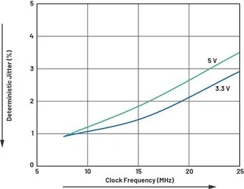
In addition to excellent clock distribution, the timing performance of the ADM3065E also supports reliable data distribution, high-speed output, and minimal additional jitter. Figure 6 shows that by using the ADM3065E, the timing constraints for RS-485 data communication are significantly relaxed. Standard RS-485 transceivers typically exhibit jitter of 10% or lower. The ADM3065E can operate at speeds exceeding 20 Mbps over cables up to 100 meters long while still maintaining 10% jitter at the receiving node. This low level of jitter reduces the risk of erroneous sampling at the receiving data node, enabling transmission reliability that standard RS-485 transceivers cannot achieve. For applications where the receiving node can tolerate jitter of up to 20%, data rates of up to 35 Mbps can be achieved over 100 meters of cable.
Figure 6. Excellent jitter performance at the ADM3065E receiving data node.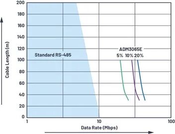
This timing performance makes the ADM3065E an ideal choice for motor control encoder communication interfaces. For each data packet transmitted using the EnDat 2.2 encoder protocol, data transmission is synchronized with the clock’s falling edge. Figure 7 shows that after the initial calculation of the absolute position (TCAL), the start bit begins transmitting data from the encoder back to the master controller. The subsequent error bits (F1, F2) indicate the specific location of faults caused by the encoder. The encoder then sends an absolute position value, starting with LS, followed by the data. The integrity of the clock and data signals is crucial for the successful transmission of positioning and error signals over long cables, with EnDat 2.2 specifying a maximum jitter of 10%. This is the maximum jitter requirement specified by EnDat 2.2 when using a 20-meter cable and a 16 MHz clock rate. Figure 4 shows that the ADM3065E can meet this requirement with a clock jitter of only 5%, while Figure 6 shows that the ADM3065E can meet the data transmission jitter requirements, which standard RS-485 transceivers cannot fulfill.
Figure 7. EnDat 2.2 physical layer and protocol for clock/data synchronization (based on EnDat 2.2 diagram implementation adjustments).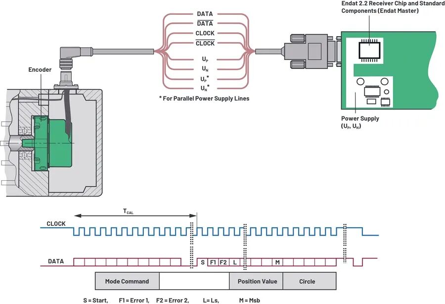
ADI characterizes the excellent cable timing performance of the ADM3065E transceiver, ensuring that system designers have the necessary information to successfully develop designs that meet EnDat 2.2 specification requirements.
Longer Cable Communication Achieves Higher Reliability

The TIA-485-A/EIA-485-A RS-485 standard requires compliant RS-485 drivers to produce a differential voltage amplitude VOD of at least 1.5 V in a fully loaded network. This 1.5 V VOD allows for a 1.3 V DC voltage drop over long cables, while RS-485 receivers require a minimum input differential voltage of at least 200 mV to operate. The ADM3065E outputs at least 2.1 V VOD when powered with 5 V, exceeding the RS-485 specification requirements.
A fully loaded RS-485 network corresponds to a 54 Ω differential load, simulating a double-terminated bus with two 120 Ω resistors, plus an additional 750 Ω from 32 unit loads (or 12 kΩ) connected devices. The ADM3065E employs a proprietary output architecture that maximizes VOD while meeting common-mode voltage range requirements, exceeding the TIA-485-A/EIA-485-A specifications. Figure 8 shows that the ADM3065E generates drive strength exceeding >210% of RS-485 standard requirements when powered with a 3.3 V rail, and >300% when powered with a 5 V rail. This expands the communication range of the ADM3065E series, supporting more remote nodes and higher noise tolerance compared to conventional RS-485 transceivers.
Figure 8. The ADM3065E outperforms RS-485 driver requirements across a wide power range.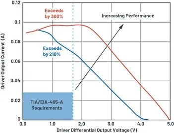
Figure 9 further illustrates this with typical application performance over 1000 meters of cable. When communicating over standard AWG 24 cable, the performance of the ADM3065E is 30% higher than that of standard RS-485 transceivers—30% higher noise tolerance at the receiving node, or an increase of maximum cable length by 30% at low data rates. This performance is particularly suitable for wireless infrastructure applications with RS-485 cables extending hundreds of meters.
Figure 9. The ADM3065E provides excellent differential signaling for ultra-long-distance applications.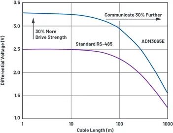


RS-485 signals use balanced differential transmission, which inherently provides some immunity to interference. System noise is equally coupled to each wire in the RS-485 twisted pair cable. The twisted pair causes the generated noise currents to flow in opposite directions, canceling out the electromagnetic fields coupled to the RS-485 bus. This reduces the electromagnetic sensitivity of the system. Additionally, the enhanced 2.1 V drive strength of the ADM3065E supports achieving a higher signal-to-noise ratio (SNR) in communication. In long cable transmissions, such as distances of several hundred meters between ground and wireless base station antennas, enhanced SNR performance and excellent signal integrity ensure accurate and reliable tilt/position control of antennas.
Figure 10. Cable lengths for wireless infrastructure can exceed several hundred meters.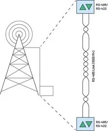
As shown in Figure 1, RS-485 transceivers require EMC protection, as they connect directly to the outside world through adjacent connectors and cables. For example, ESD on exposed RS-485 connectors and cables from the encoder to the motor driver is a common system hazard. The system-level IEC 61800-3 standard related to EMC immunity requirements for variable speed power drive systems requires a minimum of ±4 kV (contact)/±8 kV (air) ESD protection per IEC 61000-4-2. The ADM3065E exceeds this requirement, providing ±12 kV (contact)/±12 kV (air) ESD protection per IEC 61000-4-2.
For wireless infrastructure applications, enhanced EMC protection is needed to prevent lightning damage. Adding one SM712 TVS and two 10 Ω series resistors at the ADM3065E input can enhance EMC protection, providing up to ±30 kV ESD protection per IEC 61000-4-2 and ±1 kV surge protection per IEC 61000-4-5.
To improve immunity in applications with stringent electrical requirements, such as motor control, process automation, and wireless infrastructure, electrical isolation devices can be added. By utilizing ADI’s iCoupler® and isoPower® technology, current isolation with enhanced isolation and 5 kV rms transient voltage can be added to the ADM3065E. The ADuM231D provides three 5 kV rms signal isolation channels with precise timing performance, capable of reliable operation at speeds up to 25 Mbps. The ADuM6028 isolated DC-DC converter provides the required isolated power supply, rated for 5 kV rms. Using two ferrite beads can easily meet EMC-related standard requirements, such as EN 55022 Class B/CISPR 22, enabling a compact 6 mm × 7.5 mm isolated DC-DC solution.
Figure 11. Complete 25 Mbps signal and power isolated RS-485 solution with ESD, EFT, and surge protection.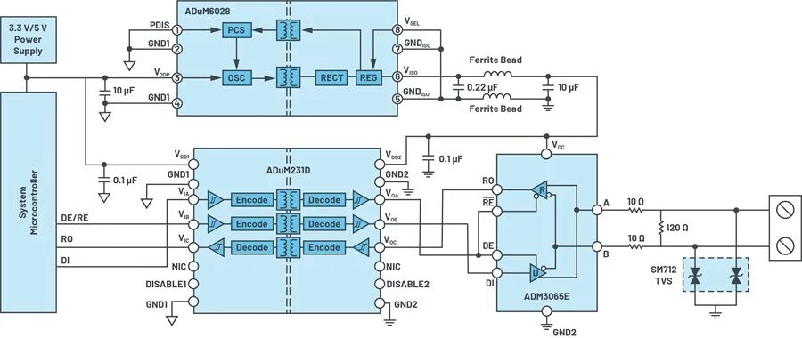


ADI’s ADM3065E RS-485 transceiver outperforms industry standards, enabling faster and longer-distance communication compared to standard RS-485 devices. Under the specified 10% jitter level in EnDat 2.2, the ADM3065E allows users to operate with a maximum cable length of 20 meters at a 16 MHz clock rate, a requirement that standard RS-485 devices struggle to meet. The drive strength of the ADM3065E exceeds RS-485 bus driving requirements by 300%, providing superior reliability and higher noise tolerance when using longer cables. Immunity can be enhanced by adding iCoupler isolation, including the ADuM231D signal isolator and the industry’s smallest isolated power solution, the ADuM6028.