Starting the debugging process based on the established development environment (for setting up the development environment, refer to nRF52832 Bluetooth Development – Setting Up Development Environment Based on VS Code (Part 1)).Since the focus is on learning Bluetooth knowledge, the development board used has a minimal design, featuring only two LEDs, two buttons, and a serial port. Other peripherals are not designed in the circuit; all I/O pins are simply routed out, powered via USB, and the serial port is also routed out via the CH340 chip.Overall layout of the nRF52832 development board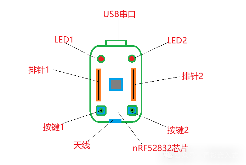 Circuit of the development boardModulesUSB-TTL Circuit:
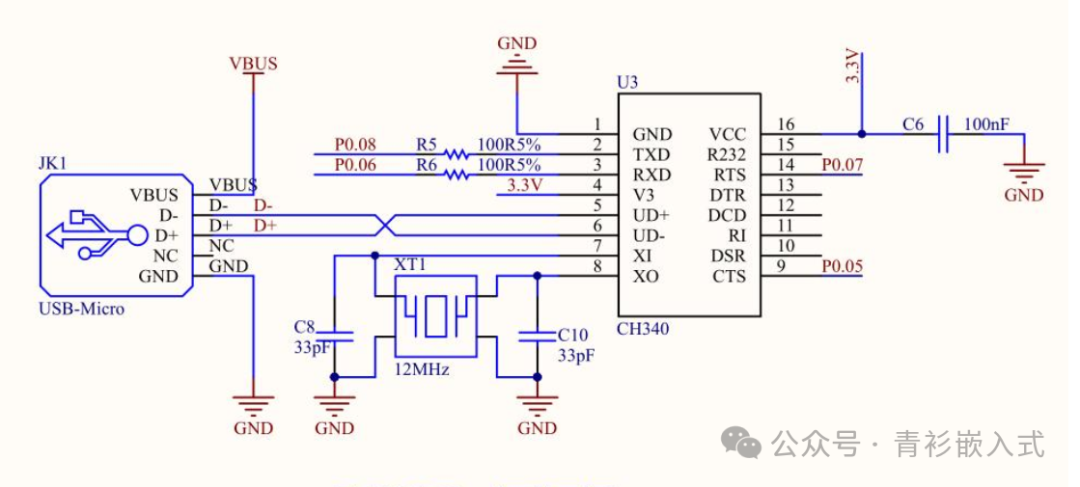 LED Circuit:
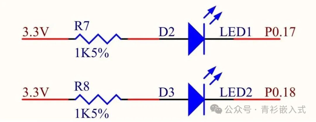 Button Circuit:
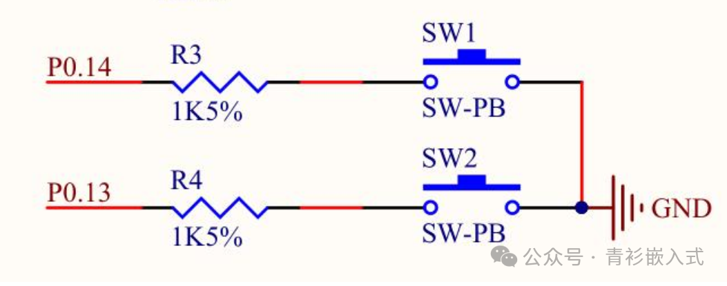 Pin Header Circuit:
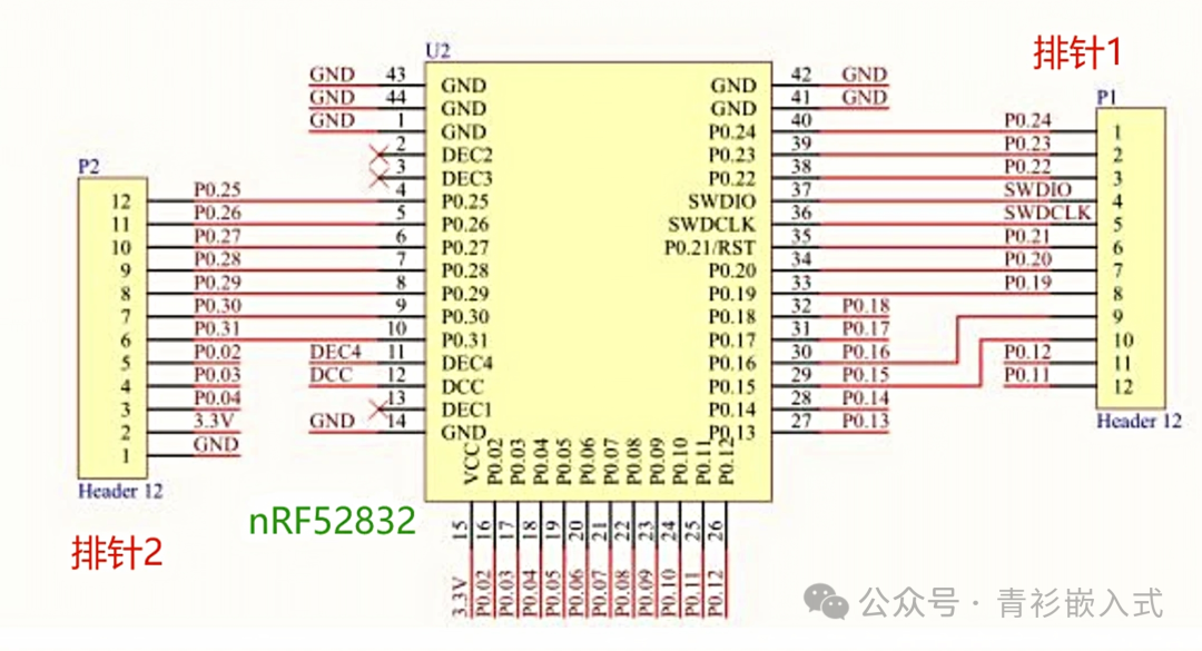 Code Project ConstructionThe project is built based on the official nRF52832 SDK, selecting the latest version 17.1.0. The official SDK source download link ishttps://www.nordicsemi.com/Products/Development-software/nrf5-sdk/download#infotabs, in addition to the SDK directory, new directories for board, libs, and projects have been created. The current directory structure of the project is as follows:
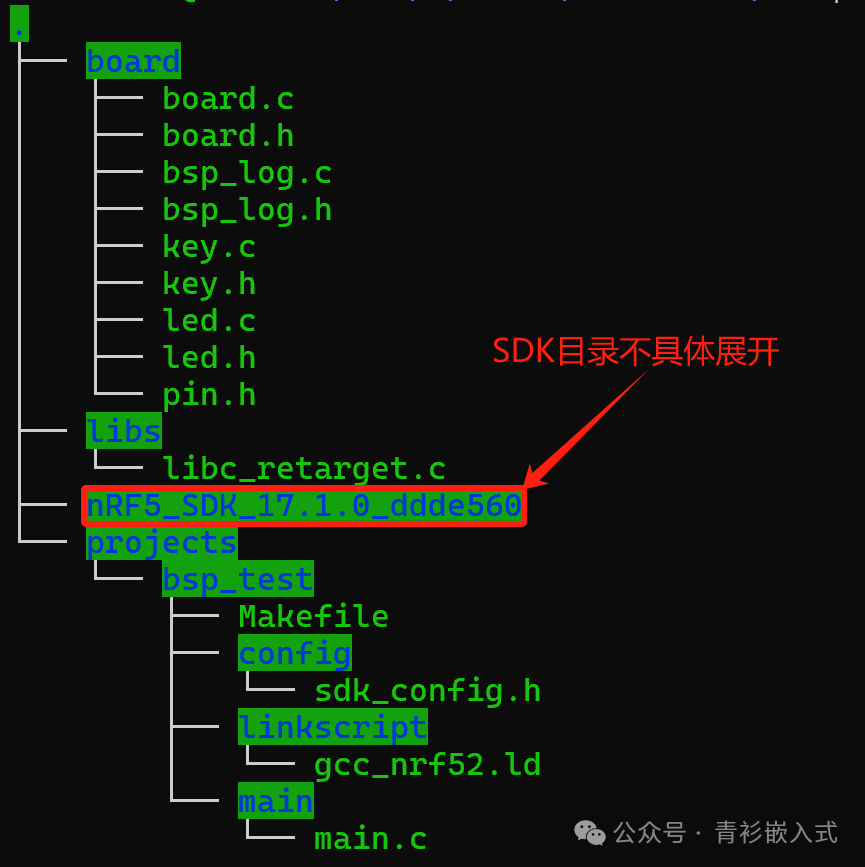 Descriptions of each directory are as follows:
| Directory Name | Description |
| board | BSP code, implementing initialization for buttons, LEDs, and logs |
| libs | Currently contains libc-related library functions |
| nRF5_SDK_17.1.0_addde560 | nRF52832 SDK, download link ishttps://www.nordicsemi.com/Products/Development-software/nrf5-sdk/download#infotabs |
| projects | Directory for storing code for future development projects |
The open-source link for the project is https://gitee.com/qingshan1206/nrf52832_study, Git has been installed during the development environment setup, and it can also be used to download directly.
git clone https://gitee.com/qingshan1206/nrf52832_study.gitLED Code Descriptionboard/led.c, provides initialization and control functions for the LED
/*LED initialization, sets GPIO to output mode, default is off*/void led_init(void);/*Turn on LED*/void led_on(led_t led);/*Turn off LED*/void led_off(led_t led);/*Toggle LED state*/void led_toggle(led_t led);Button Code Descriptionboard/key.c,provides pin initialization for buttons, registers button functions, i.e., what actions to take when a button is pressed, and provides button state querying
/*Button initialization, mainly sets GPIO to input mode and enables interrupts, triggering an interrupt when the button is pressed*/void key_init(void);/*Button registration, used to register actions when the button is pressed*/void key_register_handler(key_t key, void (*handler)(void));/*Used to query if the button is currently pressed*/bool key_is_pressed(key_t key);Log Code Descriptionboard/bsp_log.c,mainly initializes the Log component, log output depends on configuration, can output to SEGGER RTT or serial port;
/*Initialize log module*/void bsp_log_init(void){ APP_ERROR_CHECK(NRF_LOG_INIT(NULL)); NRF_LOG_DEFAULT_BACKENDS_INIT();}Retarget Code Descriptionlibs/libc_retarget.c,mainly implements the underlying functions of libc and implements _read and _write, redirecting to the serial port.Application Code DescriptionThe application code is located in the projects directory, which is used to store all sub-projects. Currently, there is a bsp_test sub-project, containing Makefile, linker script, project configuration, and application code.projects/main/main.c, mainly initializes the BSP and registers the action of toggling LED2’s state when button 2 is pressed, outputs logs, and continuously toggles LED1’s state; thus, LED1 will have a cycle of turning on and off every second, and when button 2 is pressed, LED2 will turn on, and pressing button 2 again will turn LED2 off.The application code is as follows:
static void key2_handler(void){ led_toggle(LED2);}int main(void){ board_init(); key_register_handler(KEY2, key2_handler); NRF_LOG_INFO("Hi, Board started!"); while (1) { NRF_LOG_INFO("Board is running..."); led_toggle(LED1); nrf_delay_ms(1000); } return 0;}CompilationRun make in each project directory to compile, for example, compile in the projects/bsp_test directory: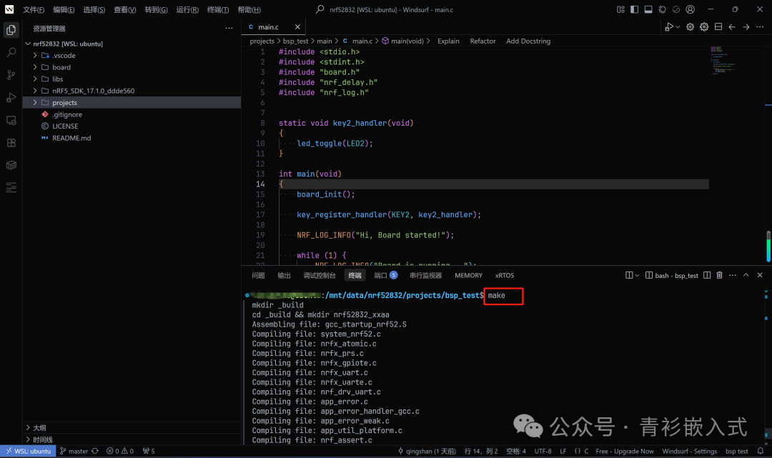 Compilation results are as follows:
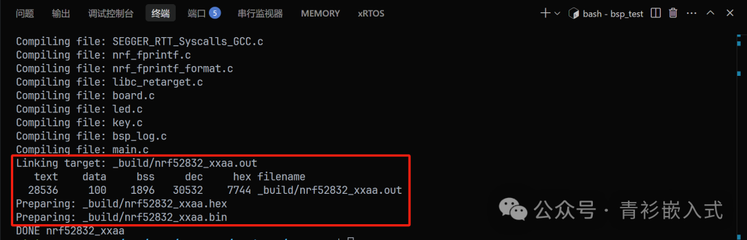 Online DebuggingConnect the JLink, click the run and debug icon on the left sidebar of VS Code to switch to the debugging page, click the start debugging button (or press F5) to start debugging, the debugging interface is as follows:
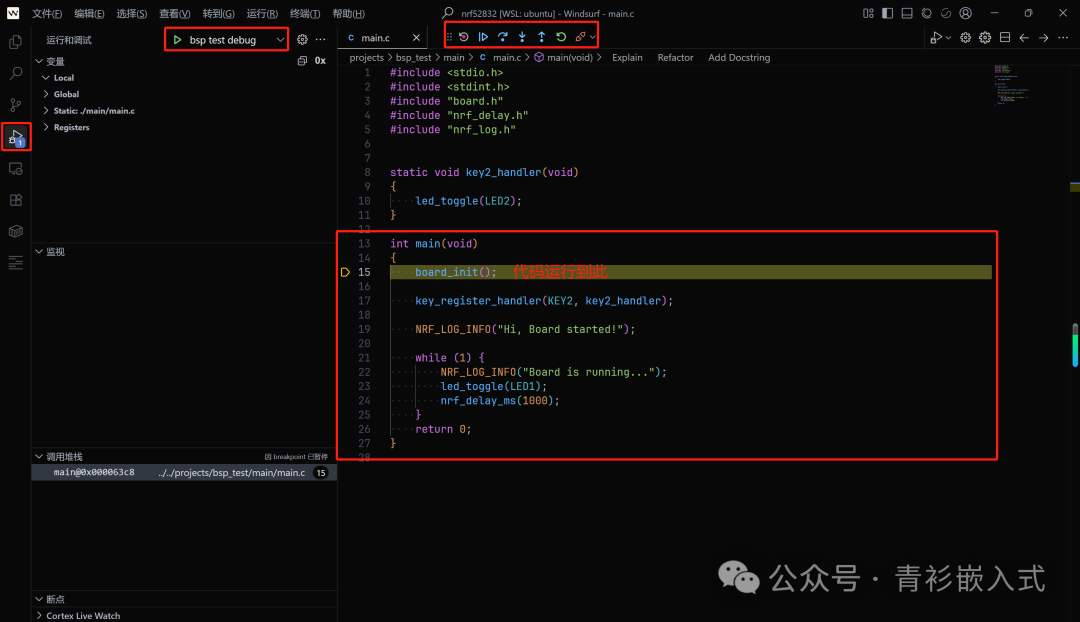 It is important to note that before starting debugging in VS Code, the configuration file must be properly written. The launch.json in the .vscode directory is the debugging configuration file, and task.json is the compilation configuration file. Since the compilation task has been added to the preLaunchTask of the debugging configuration file, it will compile first when starting debugging, and after compilation, it will enter debugging mode.
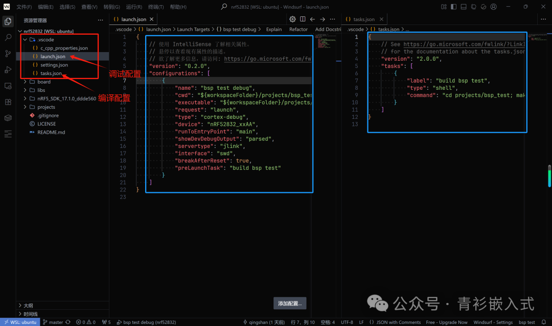 Finally, after pressing button 2, the state of LED2 changes, and the serial output result is:
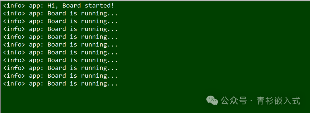 At this point, the LED, button, and serial port of the development board have all been tested successfully, and we will now proceed to the Bluetooth section.