Detailed Explanation of MODBUS TCP Communication Commands
Continuing from the previous article on the built-in MODBUS TCP command usage, the previous text only briefly mentioned the formats of three commands. Below is a detailed introduction.
SP.SOCOPEN – Confirm Link
In the list of built-in communication commands, you can see this command and its function description, as shown in the figure below:
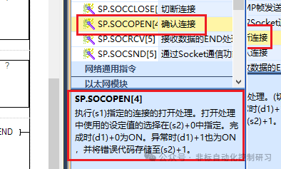
Command Format: [SP.SOCOPEN (U) (s1) (s2) (d)]
Function of each parameter:
(U): This is virtual, directly input the string “U0”, and cannot specify a tag.
(s1): Represents the link number, which is the station number, ranging from 1 to 8.
(s2): Represents the starting number of the soft element that stores control data. Therefore, it needs to occupy continuous data registers, as follows:
(s2)+0: Indicates whether the parameters used for opening the link are set by the engineering tool or by the parameters set from (s2)+2 to (s2)+6.
0000H: Indicates that the content is opened based on the settings in the “Object Device Connection Configuration” of the engineering tool.
8000H: Indicates that the settings are based on the control parameters from s2+2 to +6.
(s2)+1: Indicates the status at the end; only 0000H indicates normal termination, while other values indicate abnormal termination. Error codes can be referenced in the manual.
(s2)+2: The previously mentioned control parameters, represented by 16 bits of 0 and 1, where bit 8, 0: indicates the communication protocol is TCP/IP; bit 8, 1: indicates the communication protocol is UDP/IP. For details, please refer to the manual:
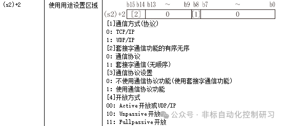
(s2)+3: Indicates the local port number, as previously mentioned, the default is 502.
(s2)+4 and +5: Indicate the IP address of the device to be linked.
(s2)+6: Indicates the port number of the device to be linked.
(d): Indicates the command end flag bit,
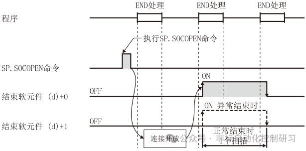
(d)+0: Indicates that this command is ON during the end processing of the scan, and OFF during the next end processing.
(d)+1: Indicates that the command is ON during abnormal termination.
Below, you can visually see the state of command execution through the timing diagram.
Below is the command programming, as shown in the figure for inputting the command:
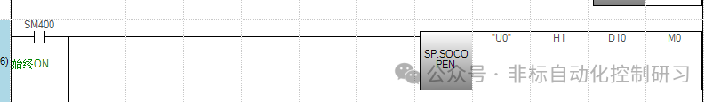
Indicates that the station number to be linked is 1, and D10 is the starting address of the control data. The settings can be assigned based on the above soft element addresses.
SP.ECPRTCL – Execute Communication Protocol
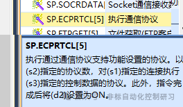
Command input format: [SP.ECPRTCL (U) (s1) (s2) (s3) (d)]
Where parameters:
(U), (s1) are the same as above.
(s2) indicates the number of protocols to be executed continuously, which is how many stations there are.
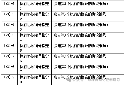
(s3) is the starting number of the soft element that stores control data. Since there may be multiple stations, this soft element will need to occupy more register addresses.
After inputting the command:
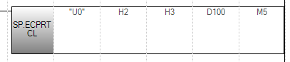
It can be represented that the current link is station 2, with a total of 3 stations, and the address for setting control data starts at D100. According to the manual, it needs to be occupied, and values need to be assigned in the register first.
SP.SOCCLOSE – Disconnect Link
Close the link specified by (S1). The status flag bit (d) is ON when completed, and (d)+0 is ON; when abnormal, (d)+1 is also ON.